Welcome back! We're in the home stretch now. Well, home-ish stretch. If you need catching up: The series introduction introduced us to the world of Ergogen, Part 1 created the points that define out layout, and Part 2 created some useful outlines for our keyboard. In Part 3 we created the basis of our keyboard's PCB, defined the footprints for our parts, and connected them all together with nets. If you're familiar with KiCAD, you can probably run off and trace the routes on your own at this point. Slap some rubber feet on the bottom of the keyboard and call it a day!
In the interest of completeness however, I'd like to take a side trip over to the last few Ergogen topics I haven't touched on just yet. Chief among these is the "Cases" section. Ergogen has functionality to export outlines as 3D objects with a depth component. The web implementation of Ergogen doesn't support exporting these files just yet however, which gives us an excuse to dabble in the world of a locally installed, offline Ergogen.
Even if you don't own a 3D printer and aren't interested in creating a case for your keyboard, running a local copy of Ergogen allows you to import custom footprints from outside of the main Ergogen GitHub repository. This chapter will use that functionality to import a mounting hole footprint, but the same theory could apply to a different microcontroller, toggle switch, or rotary encoder. Part 4 still has something for everyone.
Update: Thanks to the updates Ceoloide has made to Ergogen, much of what Part 4 covered can now be performed in the ergogen.xyz web view. It now supports integrating external footprints, and has experimental support for KiCAD previews. Working with Ergogen locally can still be useful for certain workflows, so I'm keeping this part in the guide. Just know that if all you need to do is drop a single mounting hole footprint in, there's a much more straightforward approach these days.
Commanding the Line
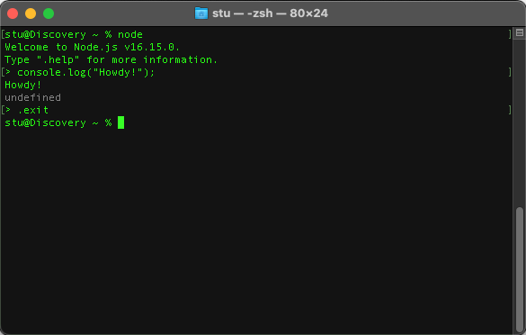
Installing Ergogen locally on your computer is thankfully a fairly straightforward process. Ergogen is written in the popular cross-platform NodeJS scripting language. As the name implies, Node leverages the Javascript, making it easily adaptable to Windows machines, Mac laptops, or Linux setups. As we saw earlier, it's also what makes it easy to create a web implementation for Ergogen.
Node install instructions vary over time and by platform. Your best guess is to mosey on over to NodeJS.org and follow their instructions there. If you're on a Mac or Linux system, you may also want to look into the Node Version Manager application if you haven't already. nvm can save you some versioning headaches in the long run if you start using Node more regularly.
Installing Node nets you more than just the scripting environment. You also get the Node Package Manager. Rather than having to fiddle with a bunch of application files and install scripts, npm lets you easily download and install Node packages from npmjs.com. These packages can be installed in one or two ways: Locally or Globally.
A local package install works like most software. It creates a folder in a specified location on your hard drive, and to use that package you need to navigate to that folder. This is useful for programs that have very isolated contexts, or apps that you may install multiple instances of.
In Ergogen's case, we don't want a single isolated instance of the tool. We want to be able to run it inside of any of our future keyboard project folders like a standard command line utility. This means we should perform a global install for Ergogen. This installs Ergogen to a Node system folder, and allows us to call the utility from anywhere on the command line.
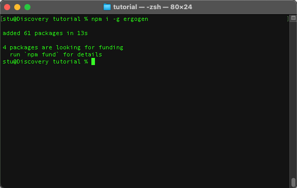
Enough command line background, let's get to it! Assuming your NodeJS install is up and running, open a command line and run:
npm i -g ergogennpm calls the Node Package Manager, i is short for install, -g is the global flag, and ergogen is the name of the package we want to install. Easy peasy.
Now that we've got Ergogen installed, go ahead and do whatever it is you usually do when starting a new coding project. In my case, I'm creating a new folder inside of ~/pcb on my system called /tutorial. This is where my Ergogen config will live, and where all the outputs will be placed. I'm also running a quick git init to create a local git repository in case I accidentally screw something up and want to roll back to an earlier state. Finally, create a file called config.yaml inside of your project folder and copy the contents of your ergogen.xyz config into it.
Now's the moment of truth. Let's run Ergogen!
ergogen config.yamlergogen is the name of our command, and config.yaml is the name of your config file. If everything goes smoothly, Ergogen will create an outputs folder and put our finished files inside of it. If you'd like to use an outputs folder with a different name, you can use the -o output_folder_name option to specify your own.
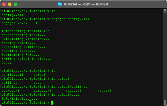
With that, we should be back to where we were with the web UI. We've got all of our .dxf outline files, as well as the .kicad_pcb file.
So far running things locally hasn't gotten us anything astounding yet. The web UI is useful for generating points and outlines, while the local instance can make constantly reloading new KiCAD files a bit easier. There are a few tricks up the local install's sleeve however. Let's first take a look at loading external footprints.
Expanding The Footprint Clan
Ergogen comes with a useful assortment of component footprints. At some point however you'll most likely want to add something a bit custom to your keyboard. In the old Ergogen v3 era you would need to fork Ergogen, add your additional footprints, and then run your new custom fork locally.
Thankfully in Ergogen v4, there's now a dedicated method for referencing external footprints. As of the time of writing this guide, this technique only works on local instances of Ergogen. The code's already there to handle bundled .zip footprint collections however, so it's only a matter of time until the web instance gets updated as well.
For this external footprint example, I'm going to use MvEerd's M2 mounting hole footprint. Creating your own custom footprint is a bit outside of the scope of this tutorial, but they're written in fairly straightforward javascript files. If you need to make a small tweak to an existing footprint, it shouldn't be too difficult to fumble your way through it. There are a lot of community footprints at this point, so poke around Github to see what else is out there, or hit up the Ergogen Discord.
Go ahead and download the M2 mounting hole footprint. ("M2" is metric shorthand for a screw with a 2mm diameter.) If you haven't downloaded individual files from GitHub before, you'll need to right click on the Raw button and download it to your computer. Make sure it keeps the mountinghole.js name. Some browsers like adding .txt onto the end of .js.
Create a new folder inside of your project folder called footprints. Place mountinghole.js inside of it.
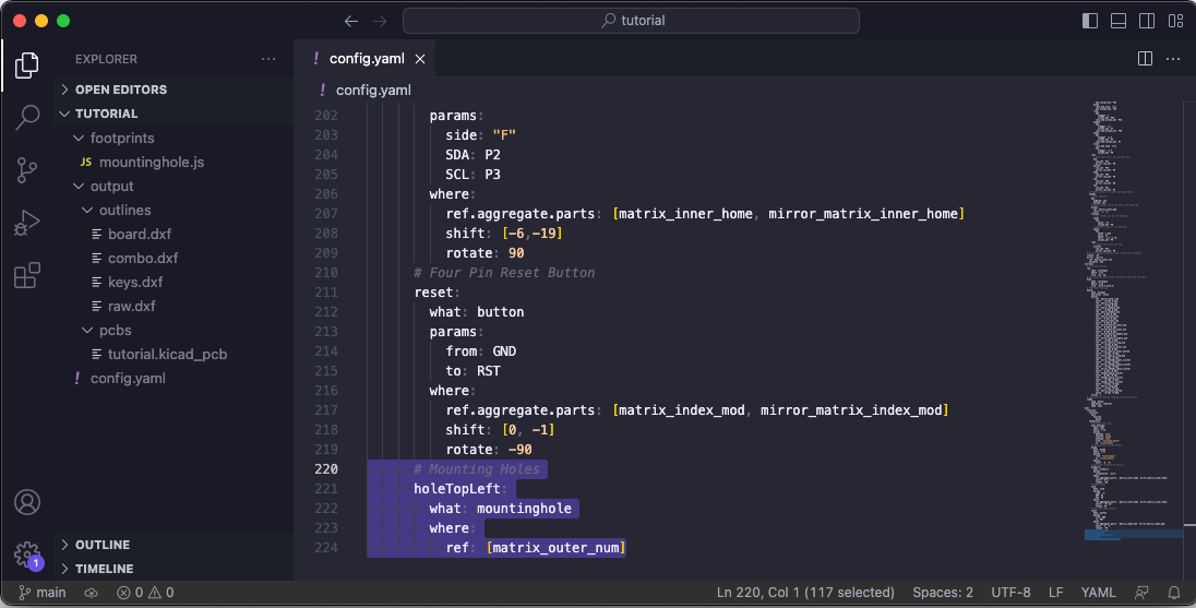
This screenshot shows the current structure of our project file. There's a few things to note here when working with external footprints. Ergogen has historically allowed you to use any file name for your .yaml config. If you named your config tutorial.yaml, all you would need to do is call ergogen tutorial.yaml for Ergogen to parse the file.
That's not the case here. When working with external footprints, it's required that you use the filename config.yaml for your Ergogen config. Secondly, we need to change how we call Ergogen. Instead of the usual ergogen config.yaml command, we need to pass our entire folder to Ergogen.
This can be accomplished easily enough. But first, let's add an example mounting hole to our config.yaml file.
units: ...
points: ...
outlines: ...
pcbs:
tutorial:
outlines:
main:
outline:
board
footprints:
choc_hotswap: ...
diode: ...
promicro: ...
oled: ...
reset: ...
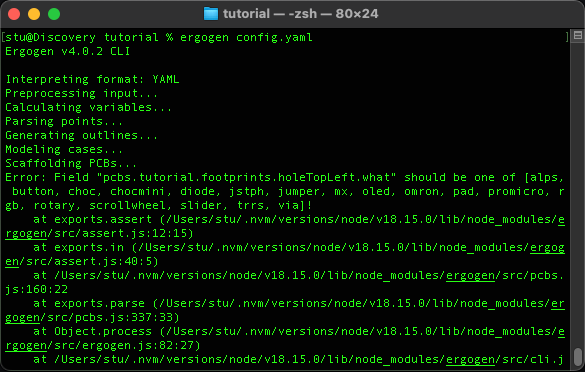
holeTopLeft:
what: mountinghole
where:
ref: [matrix_outer_num]
This should be pretty standard at this point. holeTopLeft: is the name of our footprint. what: mountinghole indicates that we'd like to use mountinghole.js for the footprint. where.ref: [matrix_outer_num] places the footprint smack dab in the middle of the top left key.
The trick here is that mountinghole.js isn't in the Ergogen GitHub repository. It's part of our local project folder. Thankfully we don't need to use any special syntax as long as we place the footprint files in the correct location. Without further ado, let's fire up Ergogen and provide it with our project folder.
ergogen .That's a bit of an anticlimax. On command lines, a single dot is shorthand for "the current folder that I'm in. By calling Ergogen this way, we're telling it that it needs to look at both the config.yaml file and all of the .js files inside of the ./footprints folder.
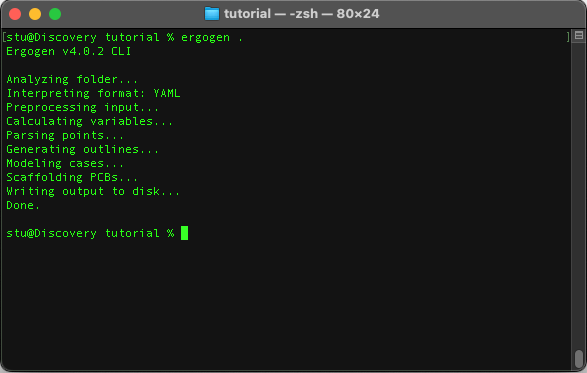
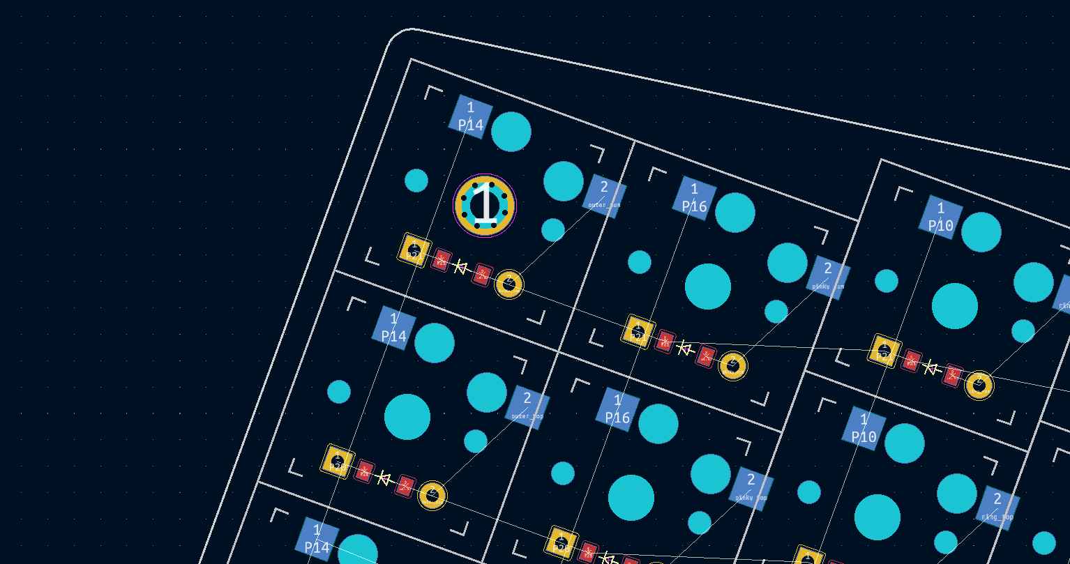
There's our mounting hole! You need to make sure all your ducks are in a row, but working with external footprints is a huge step up in Ergogen v4. I cannot stress enough that you need to call Ergogen with ergogen . instead of ergogen config.yaml
There's a ton of examples and documentation online for v3 with the config file explicitly called out. Don't get tripped up!
Mounting Holes
Mounting holes are a convenient way of attaching a case to a PCB. Our custom footprint is honestly a bit overkill. We could have just created a few circle outlines and drilled them out of our PCB as edge cuts. (You'll see this from time to time if you go poking around Github.) But now that we've got a properly drilled mounting hole, let's go ahead and add a few more.
units: ...
points: ...
outlines: ...
pcbs:
  tutorial:
    outlines:
      main:
        outline:
          board
    footprints:
      choc_hotswap: ...
      diode: ...
      promicro: ...
      oled: ...
      reset: ...
      holeTopLeft:
        what: mountinghole
        where:
          ref: [matrix_outer_num]
      holeTopInnerLeft:
        what: mountinghole
        where:
          ref: [matrix_index_num]
      holeBottomInnerLeft:
        what: mountinghole
        where:
          ref: [matrix_index_mod]
      holeTopRight:
        what: mountinghole
        where:
          ref: [mirror_matrix_outer_num]
      holeBottomRight:
        what: mountinghole
        where:
          ref: [mirror_matrix_outer_bottom]
      holeTopInnerRight:
        what: mountinghole
        where:
          ref: [mirror_matrix_index_num]
      holeBottomInnerRight:
        what: mountinghole
        where:
          ref: [mirror_matrix_index_mod]
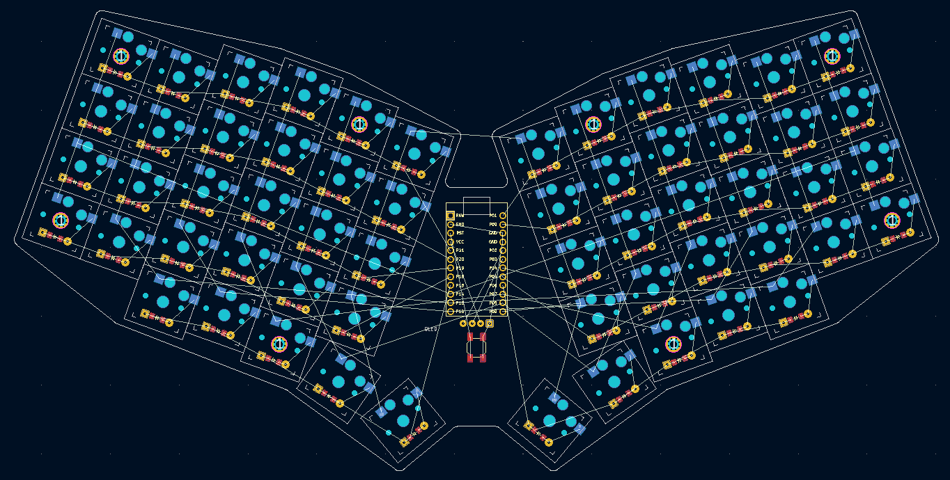
Things are looking good so far, but we've got the classic issue of having placed out footprints directly inside of one of our key switches. Let's add some shifts to move these mounting holes over.
units: ...
points: ...
outlines: ...
pcbs:
  tutorial:
    outlines:
      main:
        outline:
          board
    footprints:
      choc_hotswap: ...
      diode: ...
      promicro: ...
      oled: ...
      reset: ...
      holeTopLeft:
        what: mountinghole
        where:
          ref: [matrix_outer_num]
          shift: [0.5kx, -0.3ky]
      holeBottomLeft:
        what: mountinghole
        where:
          ref: [matrix_outer_bottom]
          shift: [0.5kx, -0.3ky]
      holeTopInnerLeft:
        what: mountinghole
        where:
          ref: [matrix_index_num]
          shift: [0.5kx, -0.4ky]
      holeBottomInnerLeft:
        what: mountinghole
        where:
          ref: [matrix_index_mod]
          shift: [0.5kx, -0.35ky]
      holeTopRight:
        what: mountinghole
        where:
          ref: [mirror_matrix_outer_num]
          shift: [0.5kx, -0.3ky]
      holeBottomRight:
        what: mountinghole
        where:
          ref: [mirror_matrix_outer_bottom]
          shift: [0.5kx, -0.3ky]
      holeTopInnerRight:
        what: mountinghole
        where:
          ref: [mirror_matrix_index_num]
          shift: [0.5kx, -0.4ky]
      holeBottomInnerRight:
        what: mountinghole
        where:
          ref: [mirror_matrix_index_mod]
          shift: [0.5kx, -0.35ky]
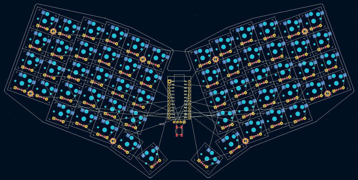
There we go! Our mounting holes have been nudged over between the keys, and shifted down slightly so that they're tucked away between the diodes. This design might be a little tight if you're using through hole diodes, but it should work fine for smd diodes.
That wraps up our last big change to the PCB. The important thing to note here is that we can use these same where: values when constructing our PCB to know exactly where each of these mounting holes go.
Making A Case
3D printing is an art form of its own. People familiar with CAD tools most likely have some idea of the type of case they'd like to design. This section isn't going to be an exhaustive treatise on keyboard case design. We're going to quickly slap something together in Ergogen to cover the bottom of our keyboard and give it a bit of color.
Let's define a simple 3D model now.
units: ...
points: ...
outlines:
  raw: ...
  keys: ...
  board: ...
  combo: ...
pcbs: ...
cases:
  bottom:
    - name: board
      extrude: 1
After everything we just went through with the PCB, cases are surprisingly straightforward. The cases: section is similar to the outlines: section of our Ergogen config file. Instead of creating flat .dxf files, it creates 3D files with depth.
The bottom: entry is a name we gave this particular 3D model. - name: board refers to the outline we defined earlier. Finally, extrude: 1 tells Ergogen to create a 3D model that is 1mm tall.
Ergogen v3 previously exported cases files in the .stl lingua franca format of 3D printing. Due to some technical issues with the .stl file creation library, Ergogen v4 exports cases as .jscad files. If you'd like to convert these into .stl files, you can use sites like openjscad.xyz or their NPM package. We're already working on the command line, so let's leverage their command line package.
npx @jscad/cli@1 output/cases/bottom.jscad -of stla -o bottom.stlThis line uses the Node Package Manager's npx command to run JSCAD as an executable. It's a whole topic worth looking into on its own, but the short story is that the above command will convert a .jscad into an .stl files for us.
If we want to run both Ergogen and JSCAD with one terminal command, we can string them together with:
ergogen . && npx @jscad/cli@1 output/cases/bottom.jscad -of stlaThis will only match the one part name of bottom.jscad however. If we'd like to get real fancy, the following command will process your Ergogen files and then convert every .jscad file in your outputs folder. Sometimes it's hard to beat a good old fashioned for loop. (The output name is implicitly understood to be the same as the input name here.)
ergogen . && for i in output/cases/*.jscad; do npx @jscad/cli@1 "$i" -of stla; done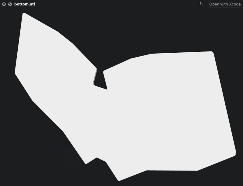
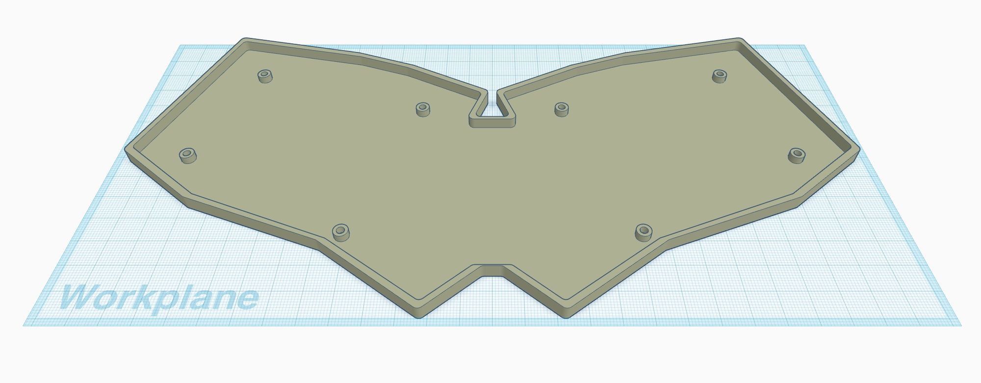
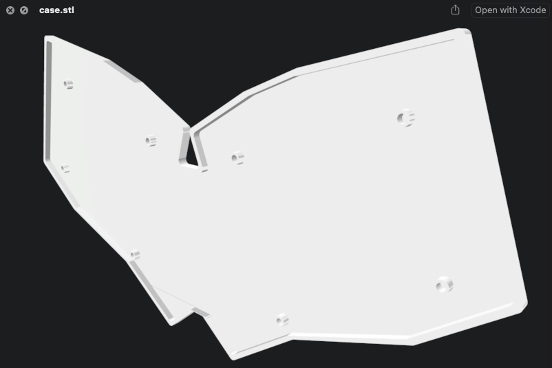
After all that, we've got a 1mm thick version of our bottom outline. Hurray?
Let's see if we can add some walls to our case design. First up, we need an outline of our board that's a few mm larger than the actual PCB design.
units:
# Proxy Spacing Variables
kx: cx
ky: cy
# Padding Variables
px: kx + 4
py: ky + 4
# Double Padding Variables
dpx: kx + 8
dpy: ky + 8
points: ...
outlines:
raw: ...
keys: ...
board: ...
xlBoard:
- what: polygon
operation: stack
points:
- ref: matrix_outer_num
shift: [-0.5dpx,0.5dpy]
- ref: matrix_ring_num
shift: [-0.5dpx,0.5dpy]
- ref: matrix_middle_num
shift: [-0.5dpx,0.5dpy]
- ref: matrix_middle_num
shift: [0.5dpx,0.5dpy]
- ref: matrix_inner_num
shift: [0.5dpx,0.5dpy]
- ref: matrix_inner_top
shift: [0.5dpx,0.5dpy]
- ref: mirror_matrix_inner_top
shift: [0.5dpx,0.5dpy]
- ref: mirror_matrix_inner_num
shift: [0.5dpx,0.5dpy]
- ref: mirror_matrix_middle_num
shift: [0.5dpx,0.5dpy]
- ref: mirror_matrix_middle_num
shift: [-0.5dpx,0.5dpy]
- ref: mirror_matrix_ring_num
shift: [-0.5dpx,0.5dpy]
- ref: mirror_matrix_outer_num
shift: [-0.5dpx,0.5dpy]
- ref: mirror_matrix_outer_bottom
shift: [-0.5dpx,-0.5dpy]
- ref: mirror_matrix_ring_mod
shift: [-0.5dpx,-0.5dpy]
- ref: mirror_thumbs_layer_cluster
shift: [-0.5dpx,-0.5dpy]
- ref: mirror_thumbs_space_cluster
shift: [-0.5dpy,-0.5dpx]
- ref: mirror_thumbs_space_cluster
shift: [0.5dpy,-0.5dpx]
- ref: thumbs_space_cluster
shift: [0.5dpy,-0.5dpx]
- ref: thumbs_space_cluster
shift: [-0.5dpy,-0.5dpx]
- ref: thumbs_layer_cluster
shift: [-0.5dpx,-0.5dpy]
- ref: matrix_ring_mod
shift: [-0.5dpx,-0.5dpy]
- ref: matrix_outer_bottom
shift: [-0.5dpx,-0.5dpy]
fillet: 2
combo: ...
pcbs: ...
cases:
bottom:
- name: board
extrude: 1
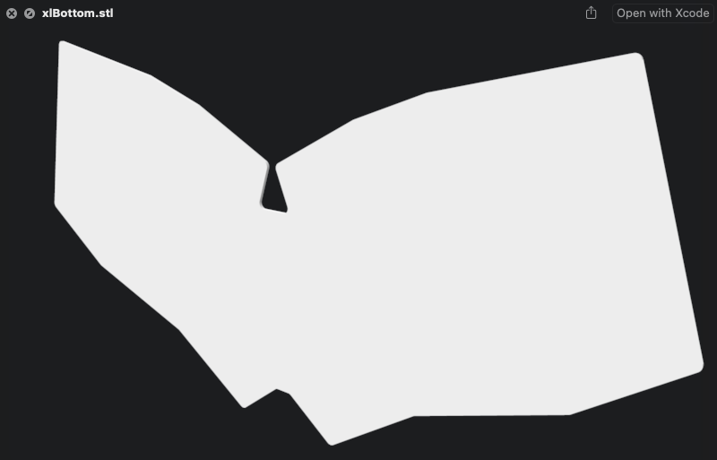
xlBottom:
- name: xlBoard
extrude: 1
Our good buddy units is back! Our original board outline used the px and py padding variables to make a board that was 2mm wider than it absolutely needed to be. dpx and dpy are adding another 2px onto the outside of our new xlBoard outline. Just as before we were able to create a 1mm case file called xlBottom.
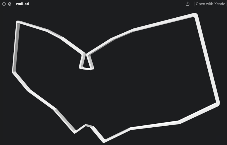
...okay. So we have a slightly bigger bottom board. Does that get us anything? Well, cases can be added and subtracted to just like we did with the combo outline in Part 2. If we subtracted board from xlBoard, we'd start getting something that resembles a wall.
cases:
  bottom:
    - name: board
      extrude: 1
  xlBottom:
    - name: xlBoard
      extrude: 1
  _outerWall:
    - name: xlBoard
      extrude: 4
  _innerWall:
    - name: board
      extrude: 4
  wall:
    - what: case
      name: _outerWall
      operation: add
    - what: case
      name: _innerWall
      operation: subtract
Now that's starting to look like a case! We even got to introduce a bit more syntactic flare to our config. Prefixing an outline or case with an underscore will signal to Ergogen that it doesn't need to export a particular asset to our outputs files. It can still be referenced by other cases however, which is exactly what we did here.
_outerWall and _innerWall were 4mm repeats of what we've seen before. wall is a bit new however. Instead of creating a new case object, we combined two together. The what: property defaults to an outline when working with cases, so we had to be explicit here that we wanted to refer to one of our earlier case files. name: tells Ergogen which case files we'd like to reference. operation: meanwhile tells Ergogen what we'd like to do to those particular case file. add is the default implicit option, but in this case we wanted to use operation: subtract to remove the inner option of our larger outline.
cases:
  bottom:
    - name: board
      extrude: 1
  xlBottom:
    - name: xlBoard
      extrude: 1
  _outerWall:
    - name: xlBoard
      extrude: 4
  _innerWall:
    - name: board
      extrude: 4
  wall:
    - what: case
      name: _outerWall
      operation: add
    - what: case
      name: _innerWall
      operation: subtract
  case:
    - what: case
      name: xlBottom
      operation: add
    - what: case
      name: wall
      operation: add
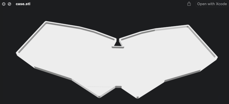
One more quick addition, and now we've got a nice stable base with some sturdy looking walls. This case piece should make a good basis for the rest of our build. Now we just need to address those mounting holes.
units:
  # Proxy Spacing Variables
  kx: cx
  ky: cy
  # Padding Variables
  px: kx + 4
  py: ky + 4
  # Double Padding Variables
  dpx: kx + 8
  dpy: ky + 8
  # Defaults to M2 Screws
  screwSize: 1
points: ...
outlines:
  raw: ...
  keys: ...
  board: ...
  xlBoard: ...
  combo: ...
  mounting:
    - what: circle
      radius: screwSize
      where:
        ref: [matrix_outer_num]
        shift: [0.5kx, -0.3ky]
    - what: circle
      radius: screwSize
      where:
        ref: [matrix_outer_bottom]
        shift: [0.5kx, -0.3ky]
    - what: circle
      radius: screwSize
      where:
        ref: [matrix_index_num]
        shift: [0.5kx, -0.4ky]
    - what: circle
      radius: screwSize
      where:
        ref: [matrix_index_mod]
        shift: [0.5kx, -0.35ky]
    - what: circle
      radius: screwSize
      where:
        ref: [mirror_matrix_outer_num]
        shift: [0.5kx, -0.3ky]
    - what: circle
      radius: screwSize
      where:
        ref: [mirror_matrix_outer_bottom]
        shift: [0.5kx, -0.3ky]
    - what: circle
      radius: screwSize
      where:
        ref: [mirror_matrix_index_num]
        shift: [0.5kx, -0.4ky]
    - what: circle
      radius: screwSize
      where:
        ref: [mirror_matrix_index_mod]
        shift: [0.5kx, -0.35ky]
pcbs: ...
cases:
  bottom: ...
  xlBottom: ...
  _outerWall: ...
  _innerWall: ...
  wall: ...
  _holes:
    - name: mounting
      extrude: 4
  case:
    - what: case
      name: xlBottom
      operation: add
    - what: case
      name: _holes
      operation: add
    - what: case
      name: wall
      operation: add
Another giant code block, but most of this should start to look a little familiar. To start with I added a new unit called screwSize: 1 to use as the radius of our screws. I then created a new outline called mounting: which reused the where.ref: and where.shift: values from our mounting holes on the PCB. (This mounting outline is a good example of including multiple shapes within a single outline by the way.) Finally, I created a new case called _holes and added it to our final case part.
You could keep going with this approach and create a basic plastic standoff design to slot onto the PCB, but we can get a much sturdier design by introducing a few extra pieces of hardware.
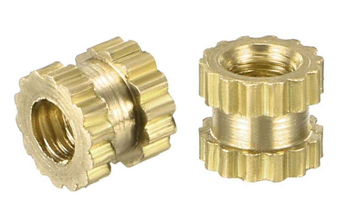
Threaded screw inserts are small pieces of metal with a screw hole in the middle. They're designed to let you add a sturdy mounting point on wooden or plastic components. They're 3.2mm wide, and 3mm tall. All you need to do to add them to your design is create a hole that's 3mm in diameter and 3mm tall. Then you use a soldering iron to warm up the screw insert and melt the last 0.2mm of plastic. Once they're in place, you just need a standard M2 laptop-style flathead screw to hold the keyboard in place.
To add support for these threaded screw inserts to our design, we need to define a second set of slightly larger mounting holes, and then subtract the inner holes from the outside holes like we did for the wall part. The outer walls will be 5mm thick, with a 3mm hollow inside.
Incidentally, these threaded screw inserts are why I had been using 4mm for some of the heights in the case section. 1mm for the base of the case plus 3mm for the standoff height is 4mm. You could get a little thinner without the standoffs, but the hotswap sockets are already 2mm thick. This design is only making the case 2mm thicker than the bare PCB itself.
Double-checking all the number just now made me realize I had undershot the wall height. The walls currently come up to the bottom of the PCB, but I want it to be flush with the top. We need to add the 1.6mm height of the PCB to the walls. Let's build our threaded screw insert standoffs and fix those heights.
units:
  # Proxy Spacing Variables
  kx: cx
  ky: cy
  # Padding Variables
  px: kx + 4
  py: ky + 4
  # Double Padding Variables
  dpx: kx + 8
  dpy: ky + 8
  # M2 Screw Inserts
  screwSize: 1.5
  standoffSize: 2.5
points: ...
outlines:
  raw: ...
  keys: ...
  board: ...
  xlBoard: ...
  combo: ...
  mounting
  standoff:
    - what: circle
      radius: standoffSize
      where:
        ref: [matrix_outer_num]
        shift: [0.5kx, -0.3ky]
    - what: circle
      radius: standoffSize
      where:
        ref: [matrix_outer_bottom]
        shift: [0.5kx, -0.3ky]
    - what: circle
      radius: standoffSize
      where:
        ref: [matrix_index_num]
        shift: [0.5kx, -0.4ky]
    - what: circle
      radius: standoffSize
      where:
        ref: [matrix_index_mod]
        shift: [0.5kx, -0.35ky]
    - what: circle
      radius: standoffSize
      where:
        ref: [mirror_matrix_outer_num]
        shift: [0.5kx, -0.3ky]
    - what: circle
      radius: standoffSize
      where:
        ref: [mirror_matrix_outer_bottom]
        shift: [0.5kx, -0.3ky]
    - what: circle
      radius: standoffSize
      where:
        ref: [mirror_matrix_index_num]
        shift: [0.5kx, -0.4ky]
    - what: circle
      radius: standoffSize
      where:
        ref: [mirror_matrix_index_mod]
        shift: [0.5kx, -0.35ky]
pcbs: ...
cases:
  bottom: ...
  xlBottom: ...
  _outerWall:
    - name: xlBoard
      extrude: 5.6
  _innerWall:
    - name: board
      extrude: 5.6
  wall: ...
  _holes:
    - name: mounting
      extrude: 4
  _standoffs:
    - name: standoff
      extrude: 4
  case:
    - what: case
      name: _standoffs
      operation: add
    - what: case
      name: _holes
      operation: subtract
    - what: case
      name: xlBottom
      operation: add
    - what: case
      name: wall
      operation: add
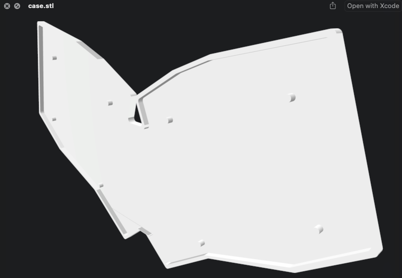
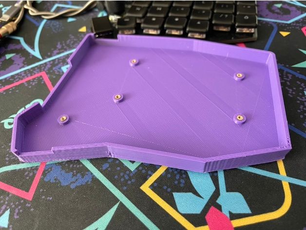
The threaded screw insert standoffs are looking great! With that, our case is finished! We've got slightly more than a minimum viable case without ever having to leave Ergogen.
If you've got something a bit more complicated in mind, it may be worth pivoting to CAD software at some point. There are beginner friendly options like Autodesk's TinkerCAD software, or more high end suites like Autodesk Fusion 360 for creating impressive beveled edges. Even if your end product isn't created from Ergogen alone, the .dxf and .stl files generated by it provide great starting points. For a more focused guide on keyboard case design theory, check out Sadek Baroudi excellent KBD News article on the topic.
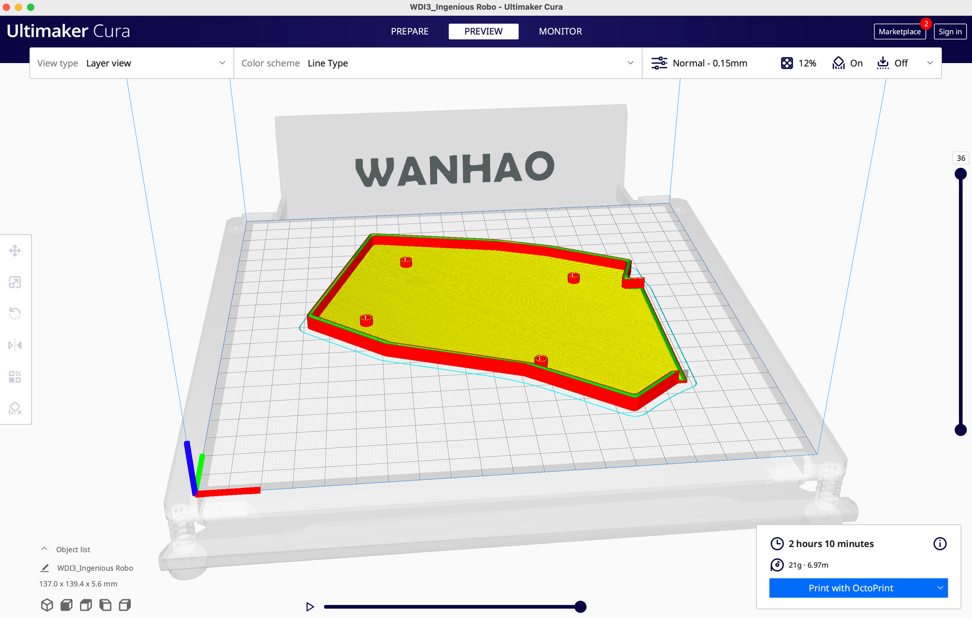
It's worth noting that if you're building a unibody keyboard like the one we designed in this tutorial, there's a good chance your keyboard will be larger than your 3D printer's print area. This case design is 273mm wide, while my printer bed is only 200mm wide. You'll probably need to split your case into at least two pieces. Each half of this design has four well-spaced standoffs, so we should be fine here.
End of Part 4
units:
  # Proxy Spacing Variables
  kx: cx
  ky: cy
  # Padding Variables
  px: kx + 4
  py: ky + 4
  # Double Padding Variables
  dpx: kx + 8
  dpy: ky + 8
  # Defaults to M2 Screws
  screwSize: 1.5
  standoffSize: 2.5
points:
  zones:
    # The primary 6x4 key matrix, plus 3 modifiers.
    matrix:
      # Position in center of KiCAD workspace.
      anchor:
        shift: [100, -100]
      # Choc spacing
      key:
        padding: 1ky
        spread: 1kx
      columns:
        # Hide the first two mods and the last mod.
        # Provide a Sofle-like column stagger.
        outer:
          rows.mod.skip: true
          key.column_net: P14
        pinky:
          rows.mod.skip: true
          key.column_net: P16
        ring:
          key:
            stagger: 5
            column_net: P10
          rows.mod.column_net: P16
        middle:
          key:
            stagger: 2.5
            column_net: P7
          rows.mod.column_net: P10
        index:
          key:
            stagger: -2.5
            column_net: P8
          rows.mod.column_net: P7
        inner:
          rows.mod.skip: true
          key:
            stagger: -2.5
            column_net: P9
      rows:
        # Four main rows, one partial row.
        mod:
          row_net: P15
          mirror.row_net: P6
        bottom:
          row_net: P18
          mirror.row_net: P5
        home:
          row_net: P19
          mirror.row_net: P4
        top:
          row_net: P20
          mirror.row_net: P0
        num:
          row_net: P21
          mirror.row_net: P1
    # Thumb cluster for Layer and Space keys.
    thumbs:
      # Choc spacing
      key:
        padding: 1ky
        spread: 1kx
      # Place thumbs where the inner mod would go.
      anchor:
        ref: matrix_inner_mod
        shift: [2, -2]
      columns:
        # Fan thumbs out by -15 degrees.
        layer:
          key:
            splay: -15
            column_net: P8
        # Spacebar uses a 1.5 wide key.
        space:
          key:
            width: 1.5kx
            splay: 75
            shift: [2.5,-3.25]
            column_net: P9
      rows:
        # Thumbs only have one row.
        cluster:
          row_net: P15
          mirror.row_net: P6
  # Mirror keyboard halves with a moderate rotation.
  rotate: -20
  mirror: &mirror
    ref: matrix_inner_num
    distance: 2kx
outlines:
  # Pure key outline.
  raw:
    - what: rectangle
      where: true
      size: [px, py]
  # Key outlines with 0.5mm removed to show key overlaps.
  keys:
    - what: rectangle
      where: true
      size: [kx-0.5,ky-0.5]
  # PCB board outline.
  board:
    - what: polygon
      operation: stack
      points:
        - ref: matrix_outer_num
          shift: [-0.5px,0.5py]
        - ref: matrix_ring_num
          shift: [-0.5px,0.5py]
        - ref: matrix_middle_num
          shift: [-0.5px,0.5py]
        - ref: matrix_middle_num
          shift: [0.5px,0.5py]
        - ref: matrix_inner_num
          shift: [0.5px,0.5py]
        - ref: matrix_inner_top
          shift: [0.5px,0.5py]
        - ref: mirror_matrix_inner_top
          shift: [0.5px,0.5py]
        - ref: mirror_matrix_inner_num
          shift: [0.5px,0.5py]
        - ref: mirror_matrix_middle_num
          shift: [0.5px,0.5py]
        - ref: mirror_matrix_middle_num
          shift: [-0.5px,0.5py]
        - ref: mirror_matrix_ring_num
          shift: [-0.5px,0.5py]
        - ref: mirror_matrix_outer_num
          shift: [-0.5px,0.5py]
        - ref: mirror_matrix_outer_bottom
          shift: [-0.5px,-0.5py]
        - ref: mirror_matrix_ring_mod
          shift: [-0.5px,-0.5py]
        - ref: mirror_thumbs_layer_cluster
          shift: [-0.5px,-0.5py]
        - ref: mirror_thumbs_space_cluster
          shift: [-0.5py,-0.5px]
        - ref: mirror_thumbs_space_cluster
          shift: [0.5py,-0.5px]
        - ref: thumbs_space_cluster
          shift: [0.5py,-0.5px]
        - ref: thumbs_space_cluster
          shift: [-0.5py,-0.5px]
        - ref: thumbs_layer_cluster
          shift: [-0.5px,-0.5py]
        - ref: matrix_ring_mod
          shift: [-0.5px,-0.5py]
        - ref: matrix_outer_bottom
          shift: [-0.5px,-0.5py]
      fillet: 2
  # Extra Large PCB board outline.
  xlBoard:
    - what: polygon
      operation: stack
      points:
        - ref: matrix_outer_num
          shift: [-0.5dpx,0.5dpy]
        - ref: matrix_ring_num
          shift: [-0.5dpx,0.5dpy]
        - ref: matrix_middle_num
          shift: [-0.5dpx,0.5dpy]
        - ref: matrix_middle_num
          shift: [0.5dpx,0.5dpy]
        - ref: matrix_inner_num
          shift: [0.5dpx,0.5dpy]
        - ref: matrix_inner_top
          shift: [0.5dpx,0.5dpy]
        - ref: mirror_matrix_inner_top
          shift: [0.5dpx,0.5dpy]
        - ref: mirror_matrix_inner_num
          shift: [0.5dpx,0.5dpy]
        - ref: mirror_matrix_middle_num
          shift: [0.5dpx,0.5dpy]
        - ref: mirror_matrix_middle_num
          shift: [-0.5dpx,0.5dpy]
        - ref: mirror_matrix_ring_num
          shift: [-0.5dpx,0.5dpy]
        - ref: mirror_matrix_outer_num
          shift: [-0.5dpx,0.5dpy]
        - ref: mirror_matrix_outer_bottom
          shift: [-0.5dpx,-0.5dpy]
        - ref: mirror_matrix_ring_mod
          shift: [-0.5dpx,-0.5dpy]
        - ref: mirror_thumbs_layer_cluster
          shift: [-0.5dpx,-0.5dpy]
        - ref: mirror_thumbs_space_cluster
          shift: [-0.5dpy,-0.5dpx]
        - ref: mirror_thumbs_space_cluster
          shift: [0.5dpy,-0.5dpx]
        - ref: thumbs_space_cluster
          shift: [0.5dpy,-0.5dpx]
        - ref: thumbs_space_cluster
          shift: [-0.5dpy,-0.5dpx]
        - ref: thumbs_layer_cluster
          shift: [-0.5dpx,-0.5dpy]
        - ref: matrix_ring_mod
          shift: [-0.5dpx,-0.5dpy]
        - ref: matrix_outer_bottom
          shift: [-0.5dpx,-0.5dpy]
      fillet: 2
  # Combination preview showing outline and keys.
  combo:
    - name: board
    - operation: subtract
      name: keys
  mounting:
    - what: circle
      radius: screwSize
      where:
        ref: [matrix_outer_num]
        shift: [0.5kx, -0.3ky]
    - what: circle
      radius: screwSize
      where:
        ref: [matrix_outer_bottom]
        shift: [0.5kx, -0.3ky]
    - what: circle
      radius: screwSize
      where:
        ref: [matrix_index_num]
        shift: [0.5kx, -0.4ky]
    - what: circle
      radius: screwSize
      where:
        ref: [matrix_index_mod]
        shift: [0.5kx, -0.35ky]
    - what: circle
      radius: screwSize
      where:
        ref: [mirror_matrix_outer_num]
        shift: [0.5kx, -0.3ky]
    - what: circle
      radius: screwSize
      where:
        ref: [mirror_matrix_outer_bottom]
        shift: [0.5kx, -0.3ky]
    - what: circle
      radius: screwSize
      where:
        ref: [mirror_matrix_index_num]
        shift: [0.5kx, -0.4ky]
    - what: circle
      radius: screwSize
      where:
        ref: [mirror_matrix_index_mod]
        shift: [0.5kx, -0.35ky]
  standoff:
    - what: circle
      radius: standoffSize
      where:
        ref: [matrix_outer_num]
        shift: [0.5kx, -0.3ky]
    - what: circle
      radius: standoffSize
      where:
        ref: [matrix_outer_bottom]
        shift: [0.5kx, -0.3ky]
    - what: circle
      radius: standoffSize
      where:
        ref: [matrix_index_num]
        shift: [0.5kx, -0.4ky]
    - what: circle
      radius: standoffSize
      where:
        ref: [matrix_index_mod]
        shift: [0.5kx, -0.35ky]
    - what: circle
      radius: standoffSize
      where:
        ref: [mirror_matrix_outer_num]
        shift: [0.5kx, -0.3ky]
    - what: circle
      radius: standoffSize
      where:
        ref: [mirror_matrix_outer_bottom]
        shift: [0.5kx, -0.3ky]
    - what: circle
      radius: standoffSize
      where:
        ref: [mirror_matrix_index_num]
        shift: [0.5kx, -0.4ky]
    - what: circle
      radius: standoffSize
      where:
        ref: [mirror_matrix_index_mod]
        shift: [0.5kx, -0.35ky]
pcbs:
  tutorial:
    outlines:
      main:
        outline:
          board
    footprints:
      # Hotswap Choc keys.
      choc_hotswap:
        what: choc
        where: true
        params:
          keycaps: true
          reverse: false
          hotswap: true
          from: "{{column_net}}"
          to: "{{colrow}}"
      # Through Hole or SMD Diodes
      diode:
        what: diode
        where: true
        params:
          from: "{{colrow}}"
          to: "{{row_net}}"
        adjust:
          shift: [0, -5]
      # Face Down Arduino Pro Micro
      promicro:
        what: promicro
        params:
          orientation: "down"
        where:
          ref.aggregate.parts: [matrix_inner_home, mirror_matrix_inner_home]
          shift: [0,0]
          rotate: -90
      # OLED Screen
      oled:
        what: oled
        params:
          side: "F"
          SDA: P2
          SCL: P3
        where:
          ref.aggregate.parts: [matrix_inner_home, mirror_matrix_inner_home]
          shift: [-6,-19]
          rotate: 90
      # Four Pin Reset Button
      reset:
        what: button
        params:
          from: GND
          to: RST
        where:
          ref.aggregate.parts: [matrix_index_mod, mirror_matrix_index_mod]
          shift: [0, -1]
          rotate: -90
      # Mounting Holes
      holeTopLeft:
        what: mountinghole
        where:
          ref: [matrix_outer_num]
          shift: [0.5kx, -0.3ky]
      holeBottomLeft:
        what: mountinghole
        where:
          ref: [matrix_outer_bottom]
          shift: [0.5kx, -0.3ky]
      holeTopInnerLeft:
        what: mountinghole
        where:
          ref: [matrix_index_num]
          shift: [0.5kx, -0.4ky]
      holeBottomInnerLeft:
        what: mountinghole
        where:
          ref: [matrix_index_mod]
          shift: [0.5kx, -0.35ky]
      holeTopRight:
        what: mountinghole
        where:
          ref: [mirror_matrix_outer_num]
          shift: [0.5kx, -0.3ky]
      holeBottomRight:
        what: mountinghole
        where:
          ref: [mirror_matrix_outer_bottom]
          shift: [0.5kx, -0.3ky]
      holeTopInnerRight:
        what: mountinghole
        where:
          ref: [mirror_matrix_index_num]
          shift: [0.5kx, -0.4ky]
      holeBottomInnerRight:
        what: mountinghole
        where:
          ref: [mirror_matrix_index_mod]
          shift: [0.5kx, -0.35ky]
cases:
  bottom:
    - name: board
      extrude: 1
  xlBottom:
    - name: xlBoard
      extrude: 1
  _outerWall:
    - name: xlBoard
      extrude: 5.6
  _innerWall:
    - name: board
      extrude: 5.6
  wall:
    - what: case
      name: _outerWall
      operation: add
    - what: case
      name: _innerWall
      operation: subtract
  _holes:
    - name: mounting
      extrude: 4
  _standoffs:
    - name: standoff
      extrude: 4
  case:
    - what: case
      name: _standoffs
      operation: add
    - what: case
      name: _holes
      operation: subtract
    - what: case
      name: xlBottom
      operation: add
    - what: case
      name: wall
      operation: add
That's it for Part 4! We configured Ergogen to run locally on the command line, imported some custom external footprints, and created a basic case file. Not bad for less than 500 lines of configuration.
With that, we're also done with Ergogen in general. We've walked through all four of the main sections of an Ergogen config, and have created an unrouted PCB and case file for our new keyboard. For the final chapter, I'll give a brief overview of the non-Ergogen steps required to build a custom keyboard. We need to route our PCB, export the circuit board files to a PCB fab, create a firmware for the keyboard, and actually build the dang thing. Time to wrap this up with Let's Design A Keyboard With Ergogen v4: KiCAD, Firmwares, & Assembly (Finale)!