Welcome back, again! In the introduction to this series we discussed the various parts of Ergogen, and in Part 1 we created a series of points defining the layout of our keyboard. Now in Part 2 we're going to focus on creating an outline for our board.
Outlines
Right now we've only defined the points. We know what layout our keys will take, but we need to give shape and structure to the actual board itself. This is done via "Outlines". They pretty much do what they say on the tin, and they can be defined a few different ways. Let's go ahead and try out the first method now.
units:
  kx: cx
  ky: cy
  px: kx + 2
  py: ky + 2
points:
  zones:
    matrix: ...
    thumbs: ...
  rotate: -15
  mirror: &mirror
    ref: matrix_inner_num
    distance: 2.5kx
outlines:
  raw:
    - what: rectangle
      where: true
      size: [kx, ky]
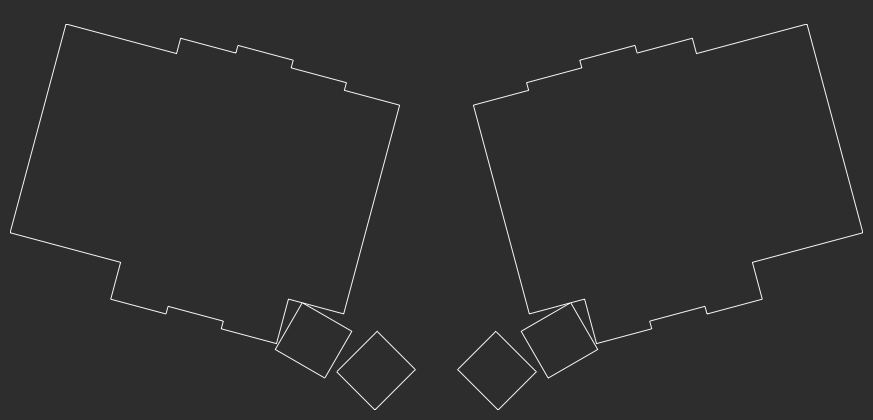
We've gone ahead and added a new top level section. Along with units and points, the outlines section will house all of our outline data. To start with, let's define a very simple outline. In this (user named) raw: section, we're going to put a border around every key on our keyboard. The - what: rectangle attribute tells Ergogen we're dealing with four sided shapes, and the where: true tells Ergogen we'd like to set this outline up anywhere we have points (keys). size: [kx, ky] tells Ergogen that we want these rectangles to have a standard Choc height and width. (We assigned cx and cy to kx and ky in the Units section of Part 1 so that we can easily re-define them later if we need to.)
Just a head's up, the - in - what: rectangle is YAML's way of indicating an item in a list. You may reciever errors from your config if your outline's - characters don't have the proper whitespace.
Anywhere that these rectangles overlap or have touch edges will be combined into the same shape. Our Choc spaced switches all overlap one another, so we get two slightly bumpy rectangles with the thumbs floating out by themselves.
points:
  zones:
    matrix: ...
    thumbs: ...
  rotate: -15
  mirror: &mirror
    ref: matrix_inner_num
    distance: 2.5kx
outlines:
  raw:
    - what: rectangle
      where: true
      size: [px, py]
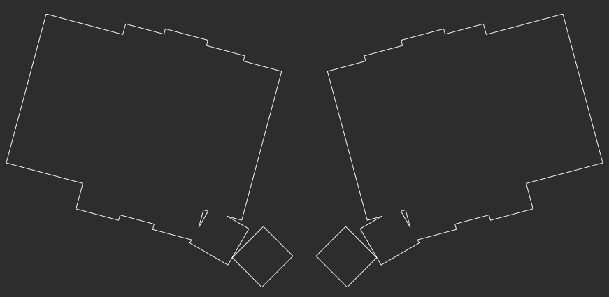
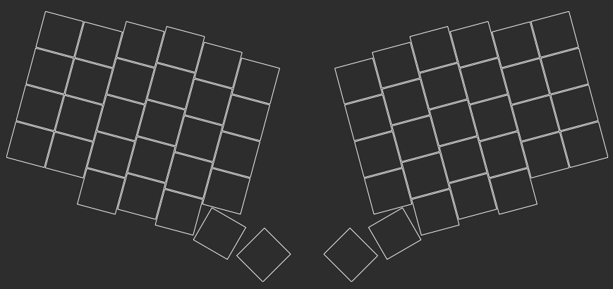
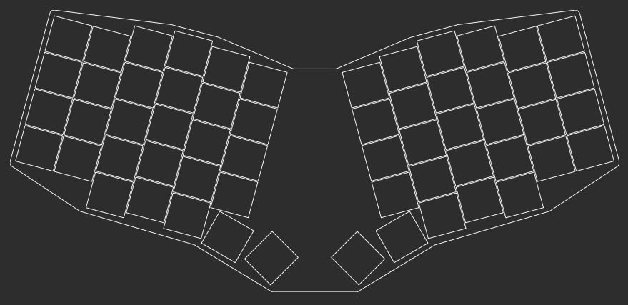
We don't have to go with our usual size: [kx, ky] exactly Choc-sized switch outlines if we don't want to. Switching over to those padded px and py units we created at the start of Part 1 will allow us to add 1mm of padding on each side of our keys. Since the raw outline is combining these keys together, the extra padding on the interior of the shape won't matter. You can see our larger thumbs start to become part of the overall shape at this point.
From here there's a few approaches we could take. We can keep using this traced-style keyboard and do some tricks to incorporate the thumbs and bridge the two halves together, or we could define our own custom keyboard shape from scratch.
Before we get into that however, we should circle back on something we discussed in the Points portion of this guide. Our ergogen.xyz preview was limited to MX spacing, and we weren't able to get a clear view of our actual keyboard layout. Let's fix that now and create an outline that's just a preview of our keys.

points:
  zones:
    matrix: ...
    thumbs: ...
  rotate: -15
  mirror: &mirror
    ref: matrix_inner_num
    distance: 2.5kx
outlines:
  raw:
    - what: rectangle
      where: true
      size: [px, py]
  keys:
    - what: rectangle
      where: true
      size: [kx-0.5,ky-0.5]
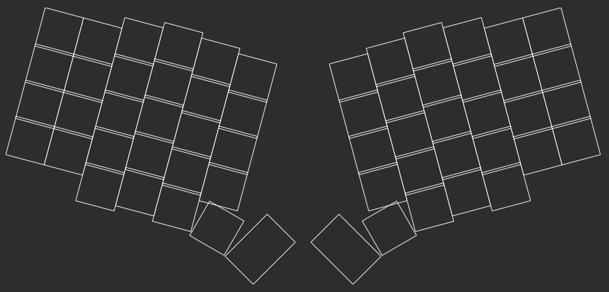
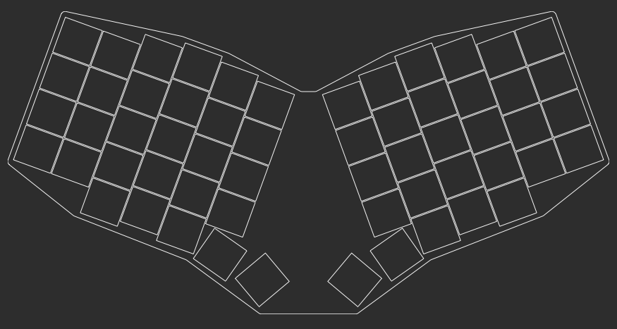
This new keys: section is very similar to our earlier raw: shape. The only difference is that we've shaved half a millimeter off of each key so that we can more easily see any potential overlap between them.
points:
  zones:
    matrix:
      key: ...
      columns: ...
      rows: ...
    thumbs:
      key: ...
      anchor: ...
      columns:
        layer: ...
        space:
            width: 1.5kx
            splay: 75
            shift: [2.5,-3.25]
      rows:
        cluster: ...
  rotate: ...
  mirror: &mirror
    ref: matrix_inner_num
    distance: 2.5kx
outlines:
  raw:
    - what: rectangle
      where: true
      bound: true
      size: [px, py]
  keys:
    - what: rectangle
      where: true
      bound: false
      size: [kx-0.5,ky-0.5]
With a better view of the thumbs, I've decided to go back and adjust the points.zones.matrix.thumbs.columns.space section. The key is now shifted over shift: [2.5, -3.25]. It's still a visual eyeball, but it seems a little better positioned than before.
Update! ergogen.xyz now supports custom preview variables! You can set$default_widthand$default_heightin theunits:section to adjust thedemo.dxfpreview. These variables only adjust the web preview, so the rest of this guide is still useful, but it's not strictly necessary to create the customkeys:preview anymore.
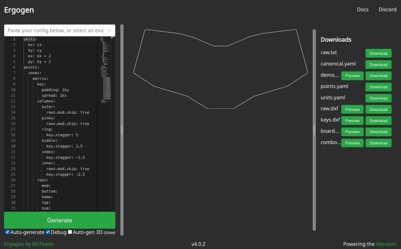
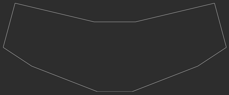
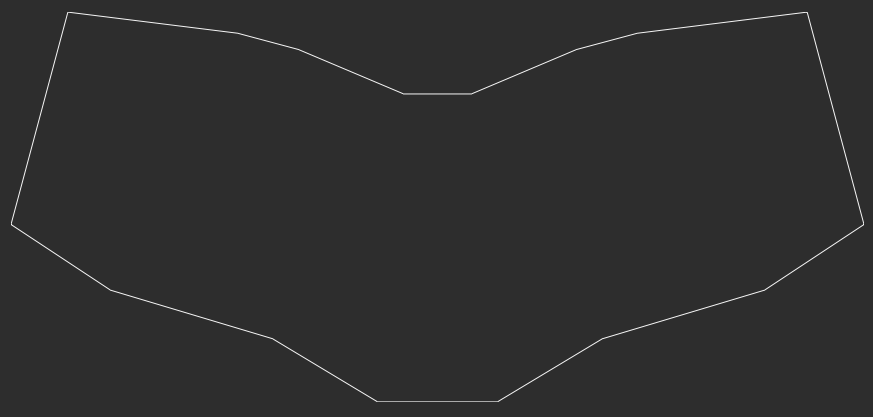
Now let's get onto the main event: Creating an actual outline for the keyboard.We want something that looks vaguely like this:
The trick is that we can't just arbitrarily draw lines on a blank canvas. We need to use the reference the points we've created to indicate where the line should be drawn.
points:
  zones:
    matrix:
      key: ...
      columns:
        outer: ...
        pinky: ...
        ring: ...
        middle: ...
        index: ...
        inner: ..
      rows:
        mod: ...
        bottom: ...
        home: ...
        top: ...
        num: ...
    thumbs:
      key: ...
      anchor: ...
      columns:
        layer: ...
        space: ...
      rows:
        cluster: ...
  rotate: ...
  mirror: ...
outlines:
  raw: ...
  keys: ...
  board:
    - what: polygon
      operation: stack
      points:
        - ref: matrix_outer_num
          shift: [0,0]
        - ref: matrix_ring_num
          shift: [0,0]
        - ref: matrix_middle_num
          shift: [0,0]
        - ref: matrix_inner_num
          shift: [0,0]
        - ref: mirror_matrix_inner_num
          shift: [0,0]
        - ref: mirror_matrix_middle_num
          shift: [0,0]
        - ref: mirror_matrix_ring_num
          shift: [0,0]
        - ref: mirror_matrix_outer_num
          shift: [0,0]
        - ref: mirror_matrix_outer_bottom
          shift: [0,0]
        - ref: mirror_matrix_ring_mod
          shift: [0,0]
        - ref: mirror_thumbs_space_cluster
          shift: [0,0]
        - ref: thumbs_space_cluster
          shift: [0,0]
        - ref: matrix_ring_mod
          shift: [0,0]
        - ref: matrix_outer_bottom
          shift: [0,0]
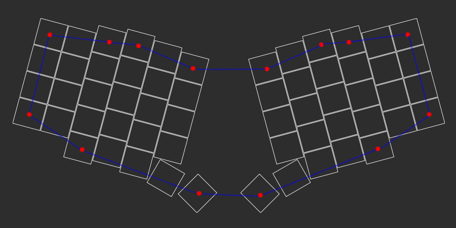
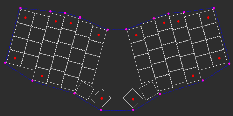
We've introduced a new type of outline here. The "polygon" outline allows us to create a many-sided shape. Each point needs a ref key to describe where it is, and can be adjusted with shift. In this particular polygon, I've started in the top left corner and walked around the board. This uses that same ref notation we discussed earlier, and has some actual examples of the mirror_ prefix. There's just one small problem: All of these points are referencing the center of the key. We need to shift the outline to the edge of the key.
outlines:
  raw: ...
  keys: ...
  board:
    - what: polygon
      operation: stack
      points:
        - ref: matrix_outer_num
          shift: [-0.5px,0.5py]
        - ref: matrix_ring_num
          shift: [-0.5px,0.5py]
        - ref: matrix_middle_num
          shift: [-0.5px,0.5py]
        - ref: matrix_middle_num
          shift: [0.5px,0.5py]
        - ref: matrix_inner_num
          shift: [0.5px,0.5py]
        - ref: mirror_matrix_inner_num
          shift: [0.5px,0.5py]
        - ref: mirror_matrix_middle_num
          shift: [0.5px,0.5py]
        - ref: mirror_matrix_middle_num
          shift: [-0.5px,0.5py]
        - ref: mirror_matrix_ring_num
          shift: [-0.5px,0.5py]
        - ref: mirror_matrix_outer_num
          shift: [-0.5px,0.5py]
        - ref: mirror_matrix_outer_bottom
          shift: [-0.5px,-0.5py]
        - ref: mirror_matrix_ring_mod
          shift: [-0.5px,-0.5py]
        - ref: mirror_thumbs_layer_cluster
          shift: [-0.5px,-0.5py]
        - ref: mirror_thumbs_space_cluster
          shift: [-0.75px,0.5py]
        - ref: thumbs_space_cluster
          shift: [-0.75px,0.5py]
        - ref: thumbs_layer_cluster
          shift: [-0.5px,-0.5py]
        - ref: matrix_ring_mod
          shift: [-0.5px,-0.5py]
        - ref: matrix_outer_bottom
          shift: [-0.5px,-0.5py]
Now that's a lot of points. I added a few additional refs as we walked clockwise around the keyboard. Most keys have a shift of 0.5px or -0.5px to shift to the left or right side of the key (with some extra padding), and 0.5py or -0.5py to move the line to the top or bottom of the key. The thumbs have a -0.75px shift since they're larger than the standard key.
This isn't an end-all-beat-all outline design method. It's just one example technique of using polygons to draw a shape that roughly outlines your board. Identifying which keys you want to be the outer edge of your outline and then figuring out how you need to shift those points to the edge can be a useful way of quickly create a rough outline of your board.
outlines:
raw: ...
keys: ...
board:
- what: polygon
operation: stack
points:
...
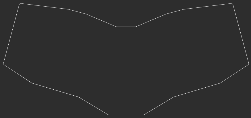
fillet: 2
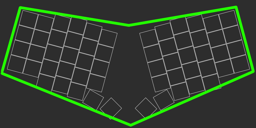
Now that we've got our outline, let's put a bit of polish on it. fillet: 2 will round the corners of the outline and give it less of a jagged look. A larger fillet value will give you a larger curve.
The last step here is to make sure everything actually fits. Let's create one last outline to do just that.
outlines:
  raw: ...
  keys:
    - what: rectangle
      where: true
      bound: false
      size: [kx-0.5,ky-0.5]
  board:
    - what: polygon
      operation: stack
      points: ...
      fillet: 2
  combo:
    - name: board
    - operation: subtract
      name: keys
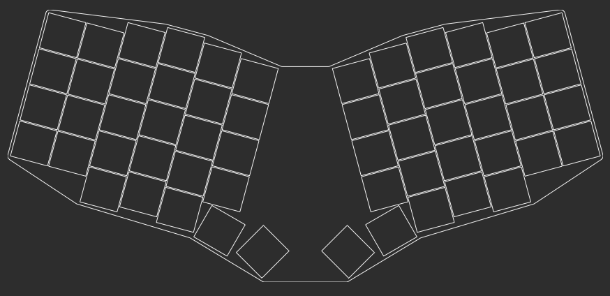
The combo: outline has some new syntax. Rather than defining a new outline, we're going to combine two previous outlines. In this case, we've subtracted the keys shape from the inside of the board shape.
You can also use - operation: add to combine two outlines together. If we had decided to use the raw outline earlier, instead of creating our large board shape, we could have just defined a simplistic middle shape to bridge the gap between the two halves. Connecting matrix_inner_num, mirror_matrix_inner_num, mirror_matrix_index_mod, and matrix_index_mod probably would have done the trick. Ergogen v3 had a glue syntax to help streamline this process but it's been depreciated with v4.
units:
  kx: cx
  ky: cy
  px: kx + 4
  py: ky + 4
Our board outline is looking pretty tight. Err, not in the slang meaning of things. The edge of the PCB were really close to the switches. Now is where we can really let those units: values we set earlier shine. Changing px and py to +4 instead of +2 immediately gives our board a nice amount of buffer.
points:
  zones:
    matrix: ...
    thumbs: ...
  rotate: -20
  mirror: &mirror
    ref: matrix_inner_num
    distance: 2.5kx
outlines:
  raw: ...
  keys: ...
  board: ...
  combo: ...
Before we wrap up this section, I wanted to take a moment to highlight just how powerful the parametric nature of Ergogen is. We were just able to update the padding on the keyboard outline by updating just two lines of text.
All of this outline creation and key placement is something one could do with enough time and patience in KiCAD. However, since Ergogen boards are defined by an easily adjusted config file, we're not stuck with the layout that we currently have. Now that we've finished laying out our board, we might decide that we want a slightly sharper angle on the board. We could update points.rotate: -15 to points.rotate: -20, giving the board a much more significant angle to it. Just like that, our entire layout has shifted. Rather than needing to lasso a bunch of switches and rejigger a board edge, we just had to change one variable. That's hard to beat.
End of Part 2
units:
  # Proxy Spacing Variables
  kx: cx
  ky: cy
  # Padding Variables
  px: kx + 2
  py: ky + 2
points:
  zones:
    # The primary 6x4 key matrix, plus 3 modifiers.
    matrix:
      # Choc spacing
      key:
        padding: 1ky
        spread: 1kx
      columns:
        # Hide the first two mods and the last mod.
        # Provide a Sofle-like column stagger.
        outer:
          rows.mod.skip: true
        pinky:
          rows.mod.skip: true
        ring:
          key.stagger: 5
        middle:
          key.stagger: 2.5
        index:
          key.stagger: -2.5
        inner:
          rows.mod.skip: true
          key.stagger: -2.5
      rows:
        # Four main rows, one partial row.
        mod:
        bottom:
        home:
        top:
        num:
    # Thumb cluster for Layer and Space keys.
    thumbs:
      # Choc spacing
      key:
        padding: 1ky
        spread: 1kx
      # Place thumbs where the inner mod would go.
      anchor:
        ref: matrix_inner_mod
        shift: [2, -2]
      columns:
        # Fan thumbs out by -15 degrees.
        layer:
          key.splay: -15
        # Spacebar uses a 1.5 wide key.
        space:
          key:
            width: 1.5kx
            splay: 75
            shift: [2.5,-3.25]
      rows:
        # Thumbs only have one row.
        cluster:
  # Mirror keyboard halves with a moderate rotation.
  rotate: -20
  mirror: &mirror
    ref: matrix_inner_num
    distance: 2.5kx
outlines:
  # Pure key outline.
  raw:
    - what: rectangle
      where: true
      size: [px, py]
  # Key outlines with 0.5mm removed to show key overlaps.
  keys:
    - what: rectangle
      where: true
      size: [kx-0.5,ky-0.5]
  # PCB board outline.
  board:
    - what: polygon
      operation: stack
      points:
        - ref: matrix_outer_num
          shift: [-0.5px,0.5py]
        - ref: matrix_ring_num
          shift: [-0.5px,0.5py]
        - ref: matrix_middle_num
          shift: [-0.5px,0.5py]
        - ref: matrix_middle_num
          shift: [0.5px,0.5py]
        - ref: matrix_inner_num
          shift: [0.5px,0.5py]
        - ref: mirror_matrix_inner_num
          shift: [0.5px,0.5py]
        - ref: mirror_matrix_middle_num
          shift: [0.5px,0.5py]
        - ref: mirror_matrix_middle_num
          shift: [-0.5px,0.5py]
        - ref: mirror_matrix_ring_num
          shift: [-0.5px,0.5py]
        - ref: mirror_matrix_outer_num
          shift: [-0.5px,0.5py]
        - ref: mirror_matrix_outer_bottom
          shift: [-0.5px,-0.5py]
        - ref: mirror_matrix_ring_mod
          shift: [-0.5px,-0.5py]
        - ref: mirror_thumbs_layer_cluster
          shift: [-0.5px,-0.5py]
        - ref: mirror_thumbs_space_cluster
          shift: [-0.5py,-0.5px]
        - ref: thumbs_space_cluster
          shift: [-0.5py,-0.5px]
        - ref: thumbs_layer_cluster
          shift: [-0.5px,-0.5py]
        - ref: matrix_ring_mod
          shift: [-0.5px,-0.5py]
        - ref: matrix_outer_bottom
          shift: [-0.5px,-0.5py]
      fillet: 2
  # Combination preview showing outline and keys.
  combo:
    - name: board
    - operation: subtract
      name: keys
On that note, that's the end of Part 2! We created an outline for our PCB, and have demonstrated the utility of the Units section we created in Part 1. Now we can finally start defining our actual PCB. Join us for the next step over in: Let's Build A Keyboard With Ergogen v4: PCBs (Part 3)!