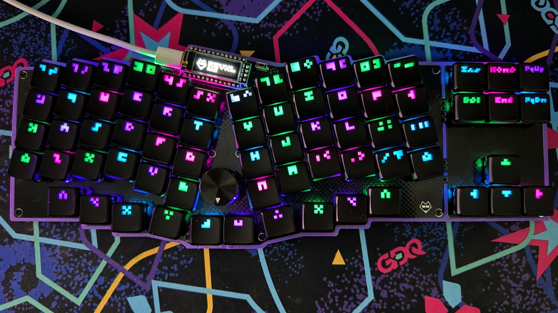
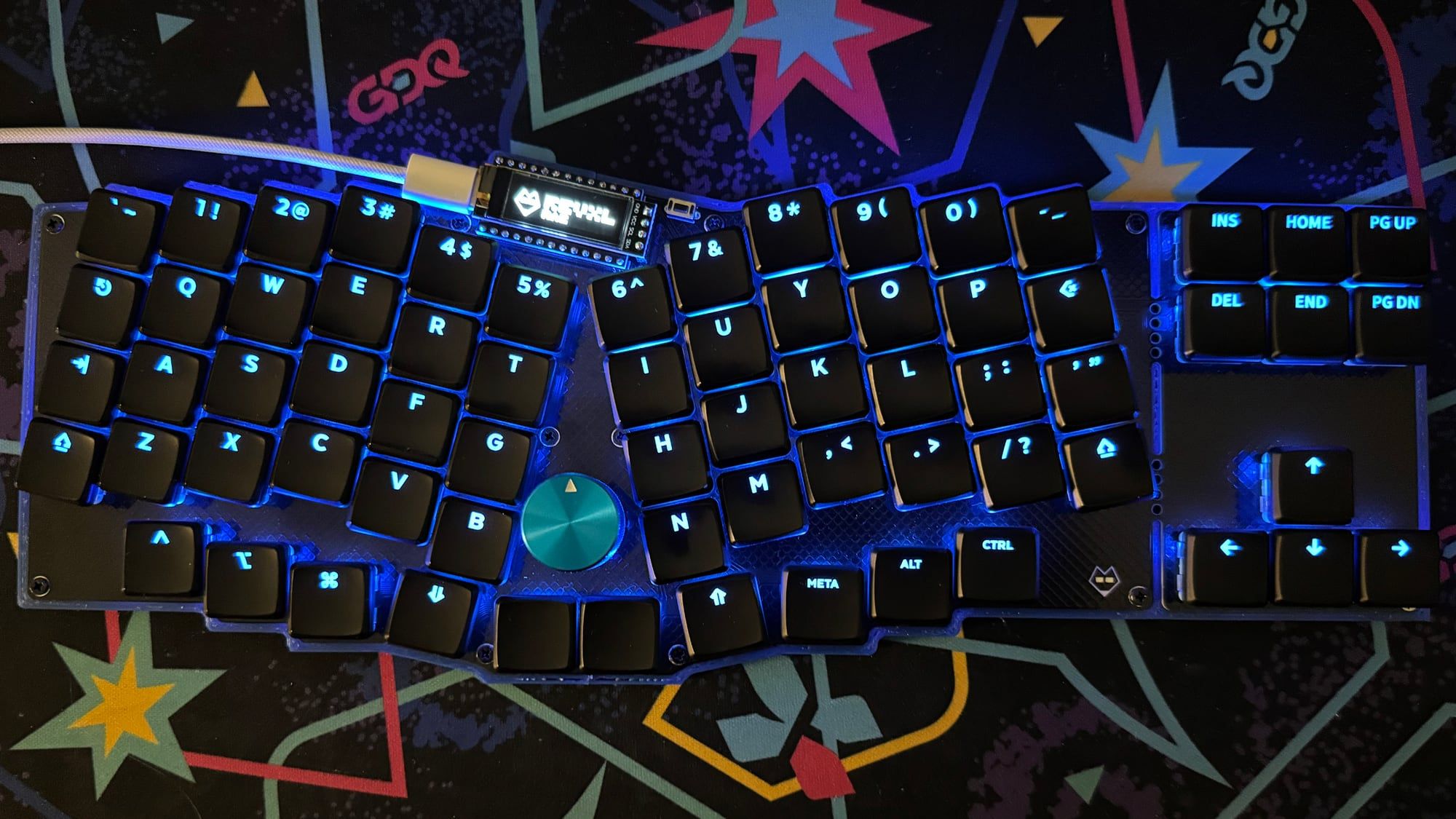
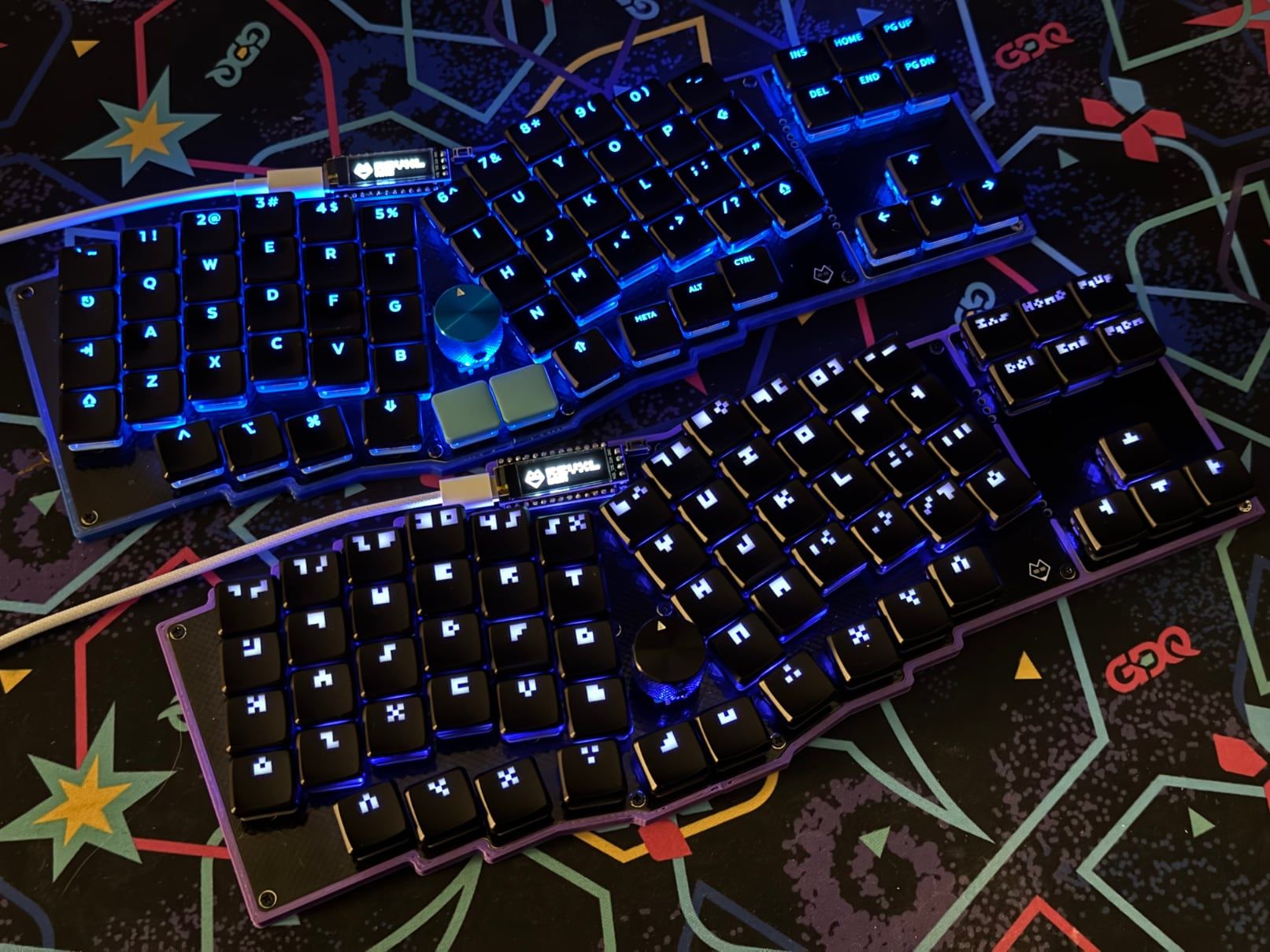
The RevXL is a maximalist Reviung-inspired ergonomic keyboard with per-key RGB LEDs, an OLED display, a rotary encoder, and a breakaway arrow cluster. It’s powered by a wired RP2040 microcontroller with QMK and Vial handling things on the firmware side. At its core, the RevXL is designed to be an on ramp to the ergonomic mechanical keyboard space. It shows off the scene’s most catchy bells and whistles while still providing a few creature comforts of more traditional layouts.
This design is a bit of a throwback for me. My journey into this strange world of ergonomic mechanical keyboards started with building a kit of the oft-praised Sofle Choc. It's a split keyboard which features RGB LEDs, an OLED Display, and a pair of rotary encoders. Noticing some similarities here? Once I was ready to start making designs of my own, I leapt straight into the world of wireless ZMK-powered keyboards with the ChonkV and the Type Boy. As much as the flashy lights and enticing knobs drove me to the Sofle, I never actually learned how to build a wired keyboard with RGB LEDs. This keyboard is a chance to backfill some of those PCB design skills I skipped over while taking the Reviung layout for a spin.
Sponsored By PCBWay

Speaking of PCB design, this project is sponsored by PCBWay. They're the internet's premier PCB fabricator and are a one-stop-shop for all your prototyping needs. They offer PCB fabrication services, 3D printing with a variety of materials, and even PCBA assembly services for those of you who prefer not to solder their own projects. If it can be represented as a design file, you can probably upload it to PCBWay and receive it a few days later in the mail.
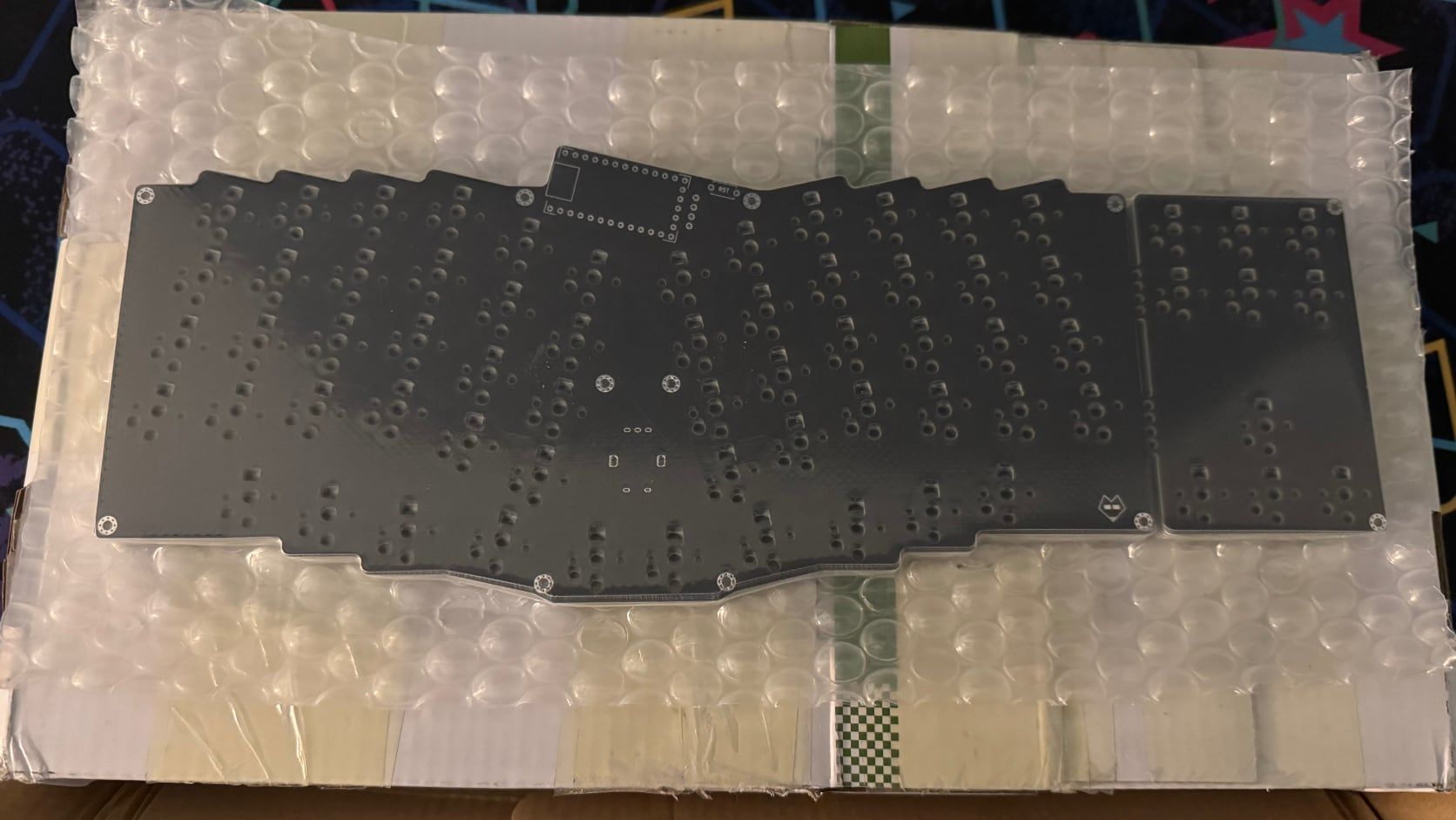
PCBWay did a great job manufacturing the RevXL PCB. The order shipped quickly, and all of the PCBs arrived safe and sound inside of a well packed box and vacuum sealed bubbled wrap. My thanks to PCBWay for helping to make this keyboard a reality.
The RevXL Layout

This keyboard is a very longwinded answer to the question, "Wait, those low profile keyboards of yours have clicky switches too?" That's right, the RevXL design is technically a Homer. After seeing me build a set of increasingly elaborate keyboards, my husband finally got low profile mechanical keyboard curious. His initial design ask had three parts: Clicky Choc switches, per-key RGB LEDs, and the layout had to have an arrow cluster that wasn't buried on a secondary layer.

As much as I like designing keyboards from scratch, Keeb.io's Cepstrum sounded like a solid fit for these design priorities. It's a split row-staggered 65% keyboard with low profile switches and per-key RGB LEDs. Unfortunately, Choc v1 switches are still relatively niche in the custom keyboard building space. There are more keycap options now than their used to be, but there are literally no shine-through options for the larger row-staggered keys. Your 1.75u Caps Lock, 2.25u Enter, and 2.75u Shift all have to go without any labels on the keys. Keeb.io's made the best of this situation by providing some near-matching blank keycaps for these modifiers, but it's a less than ideal situation aesthetically speaking.
That left us in a bit of a lurch. The obvious next steps were to either ditch the row-staggered layout, or look beyond the Choc v1 switches into the world of MX-stemmed keycaps.
FK Customs does offer low profile shine-through keycaps in the form of their new LPF profile keycaps. Paired with some Choc v2's and we'd be all set to go. I'd also just be making another 65% keyboard at that point however. Having just come off of the 65 Crimes build, I was hoping to do something a little different. I had to broach the ergonomic question.
"Just how weird can I get with this layout?"

I've been happily typing along on unusual bespoke ergonomic mechanical keyboards for the last two years. When you get into a niche hobby like this, you have to be weary that you don't delve too far off the deep end and become a weird keyboard pusher. I was all ready to accept that going beyond row stagger would be a red line for this build. To my surprise, after spending a day experimenting with my old Sofle, my husband decided to give an ergonomic layout a try. The previous ask for some dedicated arrow keys remained however. With those updated parameters in place, I got to work creating a potential layout.
I decided to use the Reviung layout as the basis of my inspiration for this build. I've always liked the striking look of Reviung keyboards, and the unibody layout would make the logistics of dealing with the RGB LEDs a bit simpler. I was already tackling some new technologies in this build. Omitting the dual microcontrollers, reversible footprints, and TRRS cable would help manage the scope of this project.
Reviung variants have featured a variety of thumb key configurations over the years. I'm particularly fond of Pete Johanson's revxlp's split spacebar design, so I shamelessly copied that for the RevXL. I'm still a sucker for dedicated number keys, and this design is supposed to be for a beginner friendly keyboard anyways, so I added a number row onto the basic Reviung41 layout.
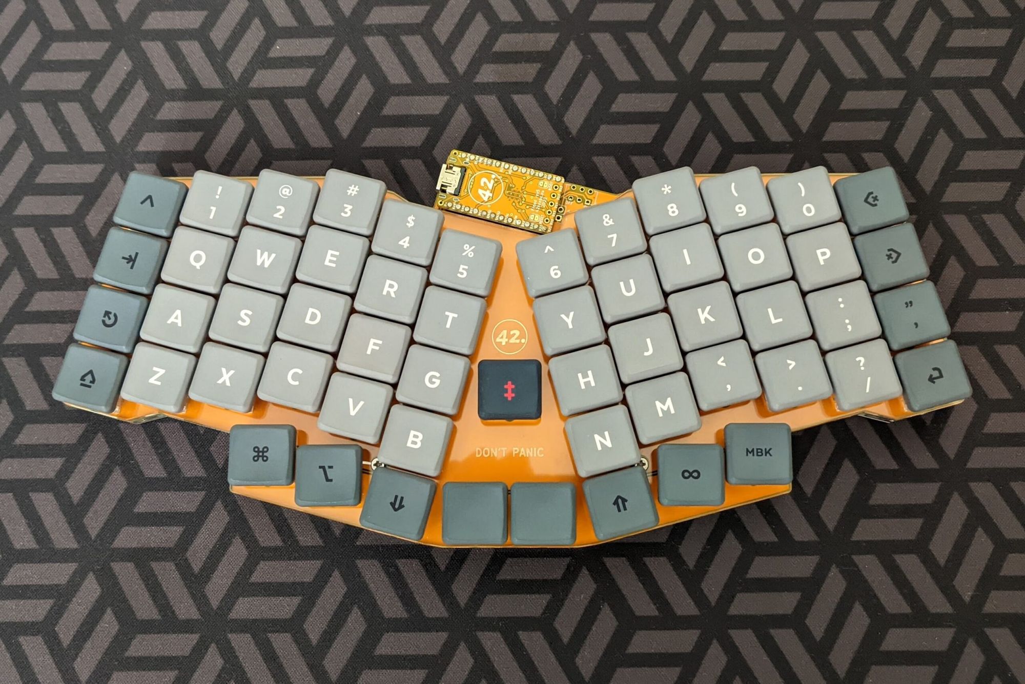
At this point I'm awfully close to 42Keebs' Rev57LP design. They've even added RGB LEDs to the latest revision of this keyboard. If you're looking for a big low profile Reviung, it's probably a much more straightforward option. They even have some nice acrylic cut cases options. The RevXL needed arrow keys however, so I was firmly in the realm making a custom design.
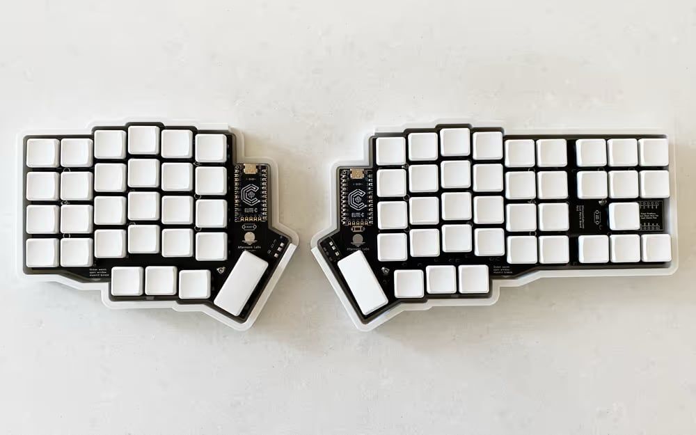
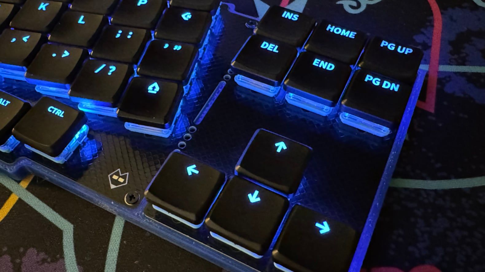
Arrow keys aren't completely unheard of in ergo mech circles. The hillside52 and Atalante have found room to sneak arrow keys into a traditional split ergonomic keyboard layout, and designs like the articulation70 have dabbled in adding entire clusters. My largest inspiration came from Afternoon Lab's Breeze keyboard however. It too is designed to be an introductory ergonomic split keyboard. It features a layout very similar to the Lily58, but with a breakaway arrow key cluster added onto the side. I always liked the idea of physically being able to "graduate" to a smaller keyboard, and the aesthetics of the optional module are pretty nice.
With those inspirations in tow I hopped into Ergogen and got to work. Thankfully this keyboard is fairly similar to the design I created in my Ergogen tutorial series. Ergogen has you break a keyboard down into a group of "points" which are used to define where the key switches and other parts should go. From there you define an "outline" which is used to create the shape of the board, and then finally the "pcb" and the 3D "case" files. This particular build doesn't have many tricks that should be unfamiliar for folks who read that series. The most substantial wrinkle is the amount of point groups I created. There's a dedicated definition for the main key groups, the modifiers, the layer keys, the spacebars, and the arrow cluster.
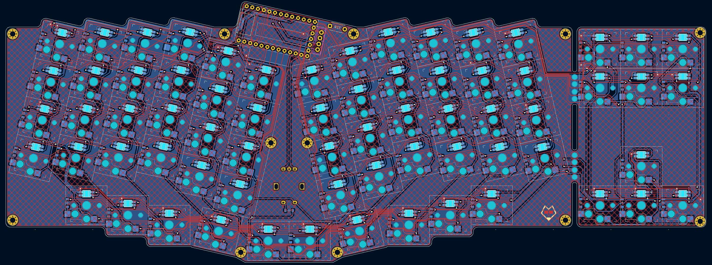
The biggest deviation from the influences I just rattled off is the PCB's overall shape. Most Reviung derivatives have a PCB outline that hugs fairly tightly to the key layout. That would work here, but then the more organic shape would just sort of be bolted onto the rounded rectangle of the arrow cluster. Instead I decided to lean into the more square shape of the arrow cluster and expanded it out to cover the rest of the Reviung layout. As you can see the rectangle doesn't quite cover all of the main keyboard, but it does so in a way that actually looks pretty nice. The top and bottom keys poke out of the keyboard's basic outline ever so slightly. It maintains the travel-friendly rectangular shape while providing just enough character to the RevXL. You almost get the sense that the keyboard's trying to break outside of the conventional box.
I usually don't write this much about a keyboard's basic layout. I drew inspiration from a lot of existing designs for this build however, and it's always good to show your work. Hopefully that bit of extra backstory will explain the maximalist character of this particular board.
RGB LEDs

The per-key RGB LEDs were one of the largest drivers of this board. QMK features all sorts of dazzling lighting effects. Strobing rainbows, green Matrix rain, velocity matched heat maps, the list goes on and on. It's a sight to behold, and thanks to the introduction of the RP2040, QMK-compatible microcontrollers now have much more storage space to contain these light shows.
The RevXL uses SK6812 MINI-E LEDs. SK6812 is the generic name for Adafruit's NeoPixels if you're familiar with that product line. The SK6812 is available in several different form factors with frustratingly different pinouts. Make sure you buy the right ones if you're working with these LEDs. The "MINI-E" variant has long legs which are more easily hand-solderable. They sit on the underside of a PCB and shine up through a hole in the PCB. Choc v1 switches have a small transparent hole in the top half to let LEDs shine through and light up the bottom of a keycap.
SK6812 LEDs operate off of a one-wire serial protocol. (The practice is affectionately known as "Bit Banging".) They're wired together in a series similar to Christmas tree lights. Each SK6812 has a Digital-In pin, a Digital-Out pin, as well as a power and ground pin. The first LED connects its input pin to your microcontroller. Then it uses its output pin to connect to the input pin of the second LED. The second LED connects its output pin to the input pin of the third LED, and you continue the chain until you get to the last LED. On the software side of things, the microcontroller is able to say, "LED 8 needs to be green right now." Each LED in the chain reads the message and determines if it has instructions for it to act on. If LED 8 reads the message, it will update its color. Otherwise it just disregards the message and passes it along the chain for the correct LED. It's a simple setup and only needs one extra data pin from your microcontroller.
The complexity comes in the wiring. Keyboards traditionally have a matrix of columns and rows. On most builds, it's not too difficult to fall into a pattern of wiring your row pins on one side of the keyboard, then placing the column routes on the reverse side of your keyboard. They generally stay out of each other's way and you can have nice repeatable patterns in your wiring. Then your LEDs get in the way and start snaking across the matrix in a complicated S-shaped pattern. Sometimes it's going left and right, other times it needs to drop down to the next row, and all the while every key now needs access to power and ground.
The trick to keeping this all neat and organized on your keyboard is, uh... You don't?
Your wiring's going to be a bit of a mess. Unfortunately your Ergogen config will be as well. (If you're not interested in how these are configured in Ergogen, feel free to hop onto the next section.)
Ergogen was designed to have nice minimalist code. You can easily specify "The far left column will all connect to Pin8" and "the middle row will all connect to Pin4." LEDs don't work like that. They need to know, "I'm LED32, I connect to LED31 and LED33." In the world of Ergogen, that means you're going to have to create an entry for every key on your keyboard.
To accomplish this, let's first start with the footprint definitions. I've included the switch, diode, and LED definitions here so you can see how they're placed in relationship to one another. (Some parameters have been committed with [...], check out the Github repo for the full code.)
footprints:
  # Hotswap Choc keys.
  choc_hotswap:
    what: switch_choc_v1_v2
    where: true
    params:
      [...]
      from: "{{column_net}}"
      to: "{{colrow}}"
    adjust:
      rotate: 180
  # SMD Diodes
  diode:
    what: diode_tht_sod123
    where: true
    params:
      from: "{{colrow}}"
      to: "{{row_net}}"
    adjust:
      shift: [-8.275, 1]
      rotate: -90
      resist: true
  # LEDs
  sk6812:
    what: led_sk6812mini-e
    where: true
    params:
      P2: "{{key.led_next}}" #DOUT
      P4: "{{key.led_prev}}" #DIN
    adjust:
      shift: [0, 5]
The SK6812 footprints are from Ceoloide's excellent ergogen-footprints repository. Since I was already importing some footprints from that repo, I'm also using his Choc and diode footprints as well.
The rotate: 180 parameter in the Choc switch ensures that the LED is shining through the top of the key. The to: and from: switch and diode parameters are unchanged from their usual configuration.
The LED footprint contains four pins. P1 maps to VCC by default, P3 maps to GND, and P2 and P4 are initially undefined Digital-Out and Digital-In pins. In this Ergogen config, we've specified a slightly unusual {{key.led_next}} and {{key.led_prev}} variable definitions. As discussed in my Ergogen tutorial, these are not fixed keyword properties in Ergogen. These are variable names that we've created ourselves. They could just as easily be called {{key.led_dout}}. All these configurations are saying is, "Look at the key: property for each point. There should be a property called led_next: and led_prev: which define the nets for this footprint."
This is where the tedious needing-to-configure-every-switch step comes in. Up in your points: definition, each column area will look like this:
points:
zones:
matrix:
[...]
columns:
outer:
key:
column_net: col0
rows:
bottom:
key:
led_prev: LED23
led_next: LED24
mirror.key:
led_prev: LED34
led_next: LED35
home:
key:
led_prev: LED12
led_next: LED13
mirror.key:
led_prev: LED45
led_next: LED46
top:
key:
led_prev: LED11
led_next: LED12
mirror.key:
led_prev: LED46
led_next: LED47
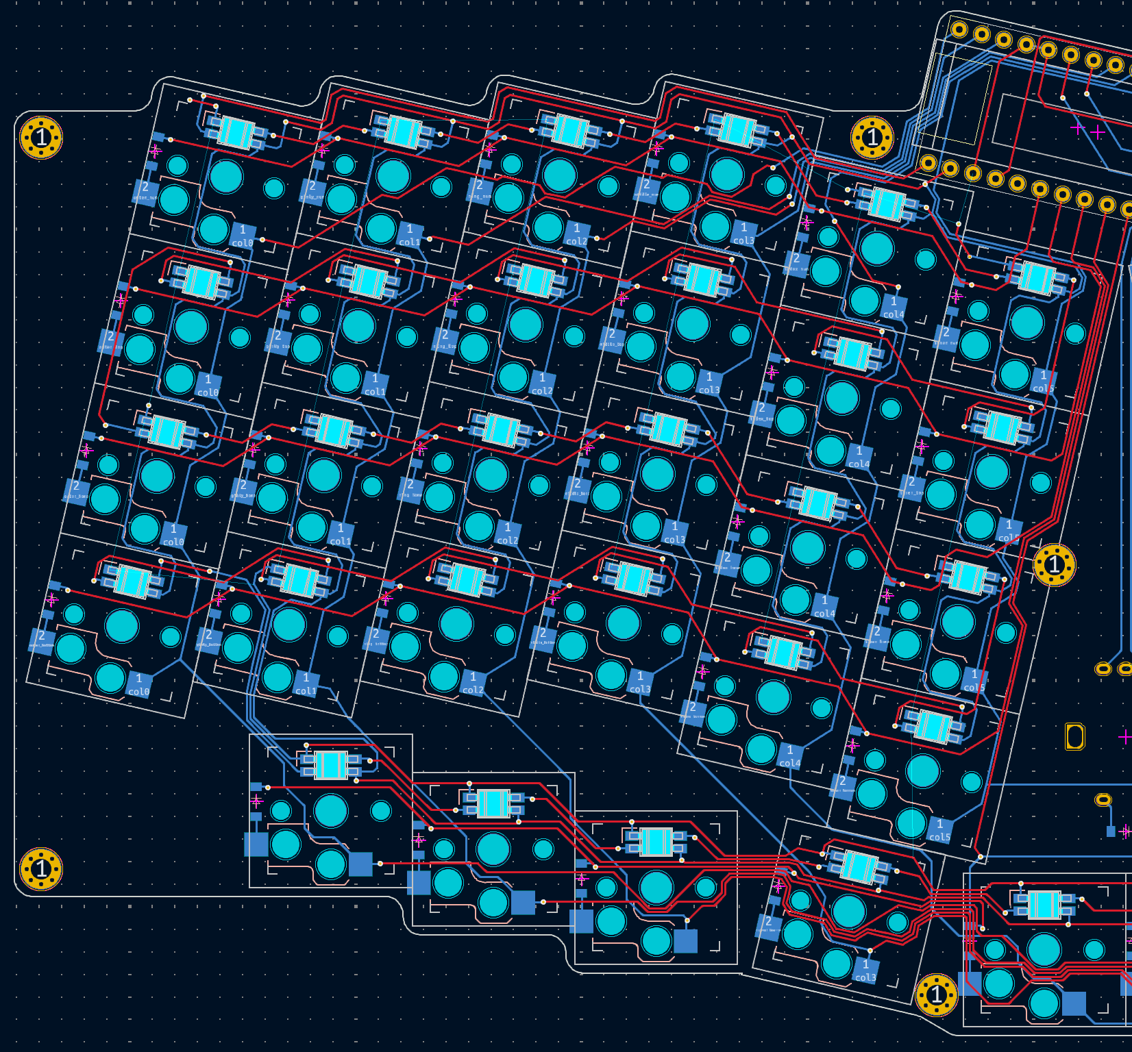
[...]Inside of each columns: section we need to create an intersecting rows: definition. This is where our key: property with the led_prev: and led_next: variable will live. Here we're able to define that matrix_outer_top has a key property of led_prev: LED11 and led_next: LED12. The next LED in the chain is matrix_outer_home with led_prev: LED12 and led_next: LED13. This continues all the way around the keyboard, including on the mirrored side with the mirror.key: properties you can see in the above example. (If it's not clear, the [...] ellipses are just truncating parts of the config.yaml file which aren't relevant for this LED example.)
The LED order is a little tricky to follow in the above example. My LEDs travel up and down each row, so in the column definitions the numbers jump pretty significantly between keys. These are the definitions for keys 12, 13, and 24 in the diagram below.
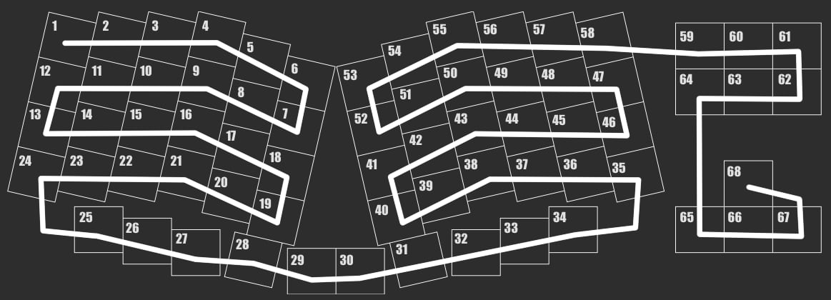
Hopefully that's enough to help you get going. It makes for a bit of a bloated config. If you have a preview of your PCB in another window, it's thankfully not that hard to define every key. I have my LED chain snake back and forth every column starting from the top left.
Screen & Rotary Encoder
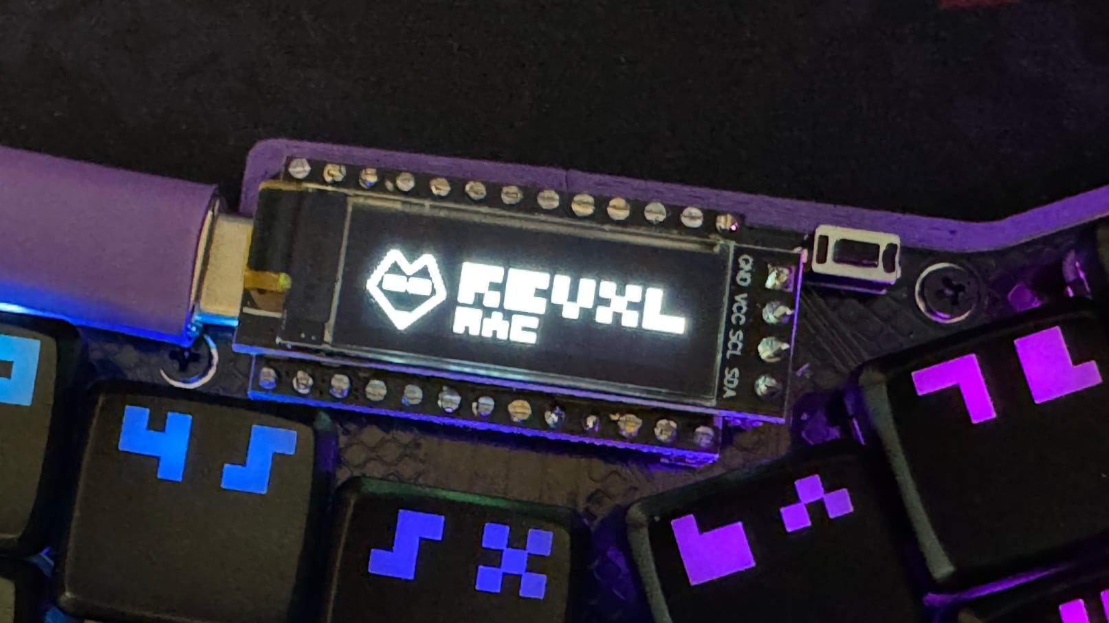
The SSD1306 display is back! This OLED screen is used commonly in mechanical keyboard builds. There's nothing too fancy here. I have a different image I'm showing for each layer in the keymap config. I haven't had a chance to kick the tires much with the screen in QMK too much, but it'll be nice to experiment with in the future.
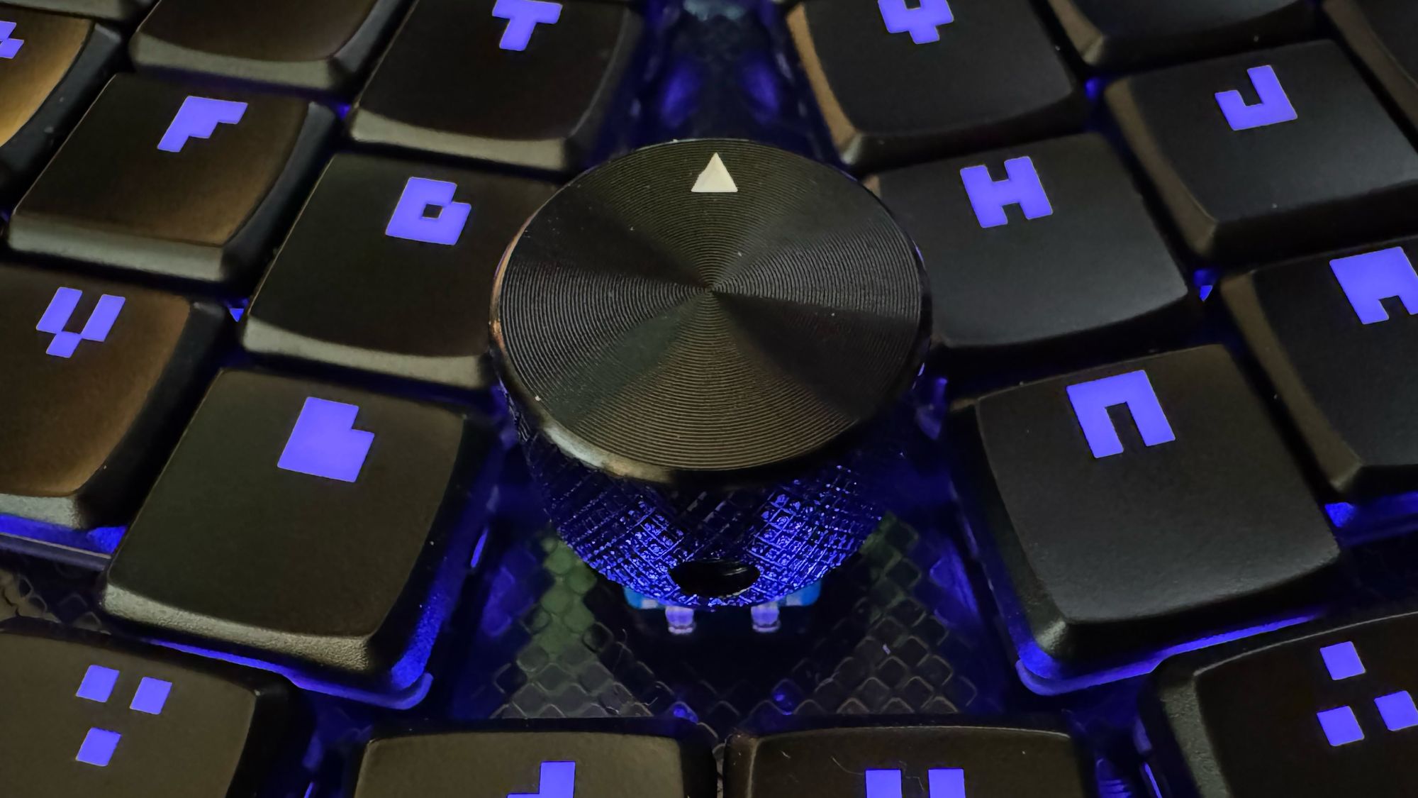
The rotary encoder is also your bog standard EC11 encoder with pushbutton action. The pushbutton is wired into the keyboard matrix with a diode like any other switch on the board. The actual rotation pieces need an additional two pins. I hadn't done much shopping for knobs before laying out the rest of the keyboard. It turns out most options are either 20mm or 25mm. The gap between the keys is closer to 24mm, so I ended up going with one of the nicer 20mm knob options.
The Breakaway Arrow Cluster

PCBs are manufactured from large sheets of FR-4 fiberglass composite and copper. Your PCB is typically manufactured on the same FR-4 sheet as several other designs. Manufacturing services will silently "panelize" a PCB before sending it through the fabrication process so that your small PCB can be cleanly snapped off from the larger sheet.
There are a variety of techniques to create these breakaway tabs. They typically use a pattern of small drill holes to weaken the structure of the PCB near the edge you need to break off. This has lead to them receiving the affectionate name of PCB "mouse bites". Sparkfun has published an entire white paper on the design of these perforated tabs.
Nothing's to stop you as a designer from including your own breakaway tabs. (Except for perhaps your PCB fab's manufacturing policies.) One interesting design option with mouse bites is that you can often send traces between perforated holes. As long as your circuit doesn't need to be a complete loop, you can include optional components on the far side of breakaway tabs. If you need those parts of the board, you can keep them intact. If you don't need those components, you can snap them off without disrupting the electronics on the main part of your circuit.
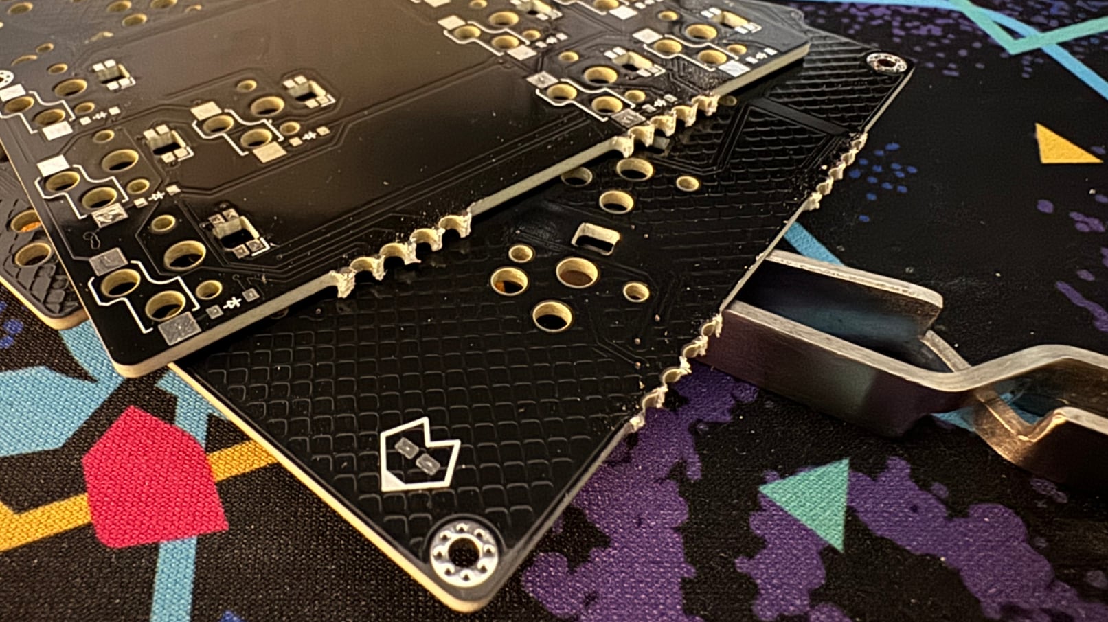
Thanks to the chain-like nature of the RGB LEDs, that means we can snap off the last 10 keys without disrupting the rest of the circuit. The keyboard matrix likewise doesn't mind the last two columns being unceremoniously snapped off. Even if this ergo mech experiment ends up being a bust for my husband, I'll still have a nice traditional Reviung board for my own use.
I'm not going to lie, part of me just likes the aesthetics of the breakaway section. I might keep the arrow keys intact even if I end up daily driving one of these boards. Flexibility in one's keyboarding is always nice. I definitely didn't follow the best practices here. I'm using large 2mm drill holes for my mouse bites similar to the Breeze keyboard. They're more like... Capybara Bites? It worked well enough for me, but it might be worth searching out some other examples if you're serious about panelization.
If you do take this same route, I highly suggest using flush cutters rather than actually snapping the PCB. Fiberglass shards can do really nasty things to the inside of one's lungs. Avoid using Dremel or sandpaper as well. Or maybe just wear eye protection and a spare KN95 you've got laying around.
Keycap Considerations
Hang on. We went over this in the layout section. This keyboard only uses 1u keycaps. We just need a copy of MBK Glow and we're good to go. Next section!
Err...
Right. So it turns out that in my haste to recreate the four arrow keys and the six other cluster keys, I never actually checked to see if the MBK Glow keycap set contained an Insert, Home, End, Page Up, or Page Down key. I'm all set with Delete, but the other arrow cluster keys would need to leverage one of the keycap set's more generic symbols.
The whole point of this layout was trying to make an aesthetically uncompromised keyboard. Whoops. No problem. I can still fix his. FK Caps has their FK Custom service! I can just print a few keycaps to round out the set. No problem!
Small problem. It turns out FK Custom has a $40 minimum purchase limit. That means you need to manufacture over custom 30 keys in a single order. Well drat. I would need to design an entire new keycap set to make it worth printing out a few extra keys.
I Designed An Entire New Keycap Set To Make It Worth Printing Out A Few Extra Keys
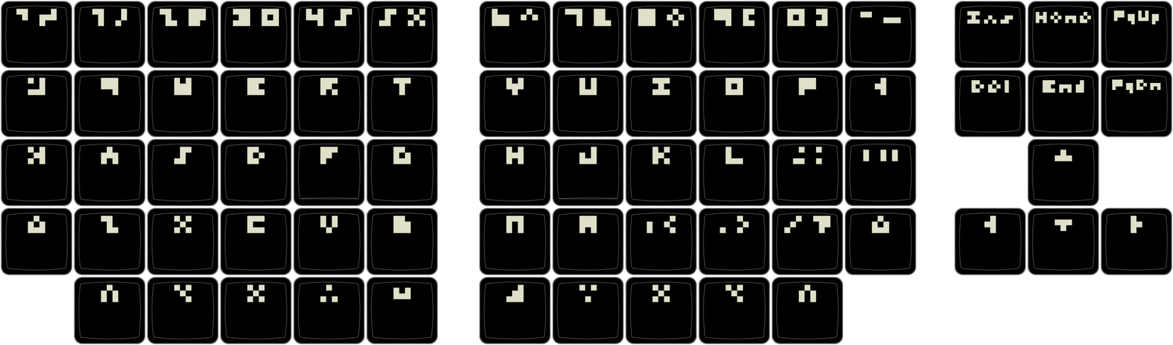
I think I may be starting to lose the plot of this particular build. I started looking into FK Custom, and the got the ball rolling on a back burner idea I've had in my head for a while. I've always liked the idea of keycap glyphs which are inscrutable at first glance, but actually start to make sense if you stare at them long enough. I had a couple of false starts down this path, but settled on a minimalist low resolution pixel look.
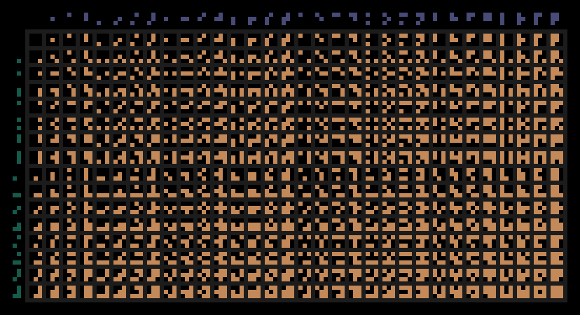
Moonbase has an excellent blog post exploring the readability of low resolution pixel fonts. 3x3 pixels is just enough resolution to start cobbling together letters. Some fare better than others. A and T are clear enough, but you have to use your imagination a bit with W and E. Some symbols rely more on context. S and 5 are both made up of the same curved few pixels. As Moonbase detail in their blog, 3x4 is when things start getting really legible. If you were building a real font, you probably wouldn't want X, %, and ⌘ to all use the same glyph. The brutalist inscrutability is the point here though, so I held off on increasing the resolution any further.
I was always planning on building one of these RevXL boards for myself. Now I'll have some visual flair for it and any other backlit RGB keyboards I make in the future. I've gotten a few asks to try this font out, so I cobble together a TrueType font based off the .svg files I made for the keycap set. Say hello to Threebee everyone. Be nice.
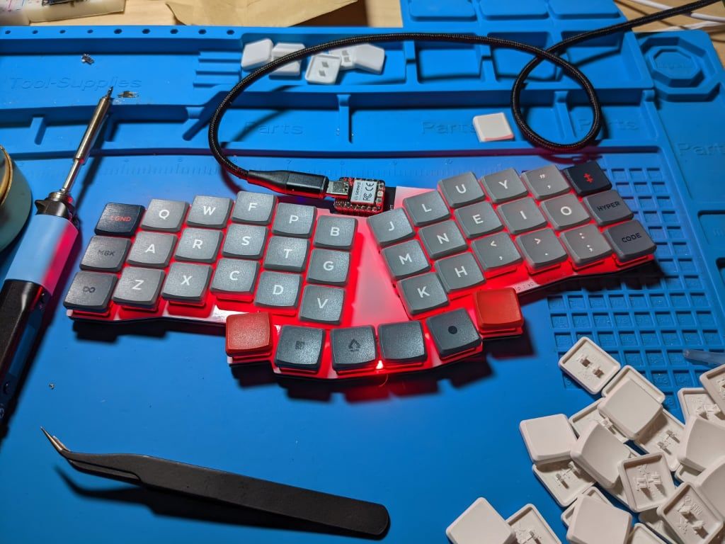
Assembly
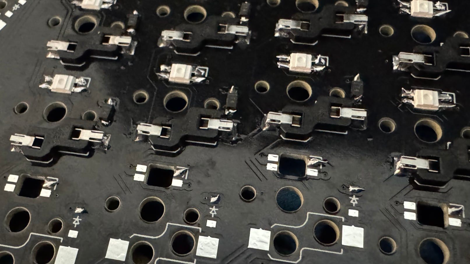
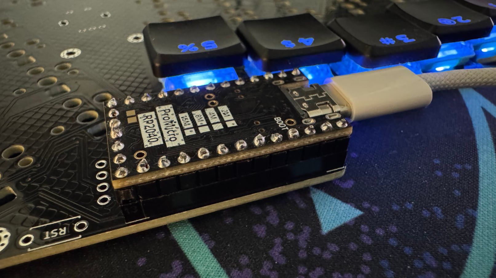
There's nothing too outside the ordinary on this build. The RevXL is designed for Choc v1 switches using Choc hotswap sockets. It uses surface mount 1N4148 diodes for the keyboard matrix. The SK6812 "MINI-E" RGB LEDs are also surface mount. Use some reverse action tweezers on the SMD components and you should be fine. It also has a lil' 2-pin 6mm x 3mm reset switch to make flashing new firmware easier. Outside of that, there's just the microcontroller stack. The RevXL takes advantage of an RP2040 in an Arduino "Pro Micro" form factor. Stacked on top is a typical 128x32 pixel SSD1306 OLED screen.
The RP2040 is the microcontroller featured in the Raspberry Pi Pico. It's designed to be a modern low cost alternative to the aging Arduino's AVR platform. The Pico is a relatively large micro controller, so the DIY community has standardized on repackaging the RP2040 in the old faithful Arduino Pro Micro form factor. The Pro Micro is about the size of two square keycaps, so it's a nice fit for mechanical keyboard builds. The RP2040 variant takes after the Elite-C microcontroller and includes a few extra pins. The extra pins make wiring up the optional components a bit easier, but we're actually here for the 16mb of onboard memory. QMK's firmware starts hitting the Arduino's memory ceiling when you add a few different RGB programs, so the RP2040 gives is a nice overhead to play around with its fancier functionalities.
When working with a microcontroller, it's a good idea to "socket" it. Rather than soldering the microcontroller directly onto the PCB, you solder some header sockets onto the PCB, and then some header pins onto the microcontroller itself. It allows you to more easily replace the microcontroller if something goes wrong.
The mechanical keyboard community commonly likes working with "machine pin headers". These sockets are unusually low profile, but I've personally never had any luck working with them. The small pins you solder onto the microcontroller have always been a little fragile for my liking. I decided to stick with standard "DuPont" header pins this time around, but I at least found a set on Aliexpress that's only 3.5mm tall.
Originally I soldered the header pins onto the microcontroller with the small black plastic protector on the bottom of the microcontroller. It made the RP2040 a little taller than usual, but it was still shorter than a Choc switch with a keycap.
Unfortunately it turns out that I had positioned the microcontroller a bit too close to the 3 key. Depending on the size of the USB-C cable you use, it can brush up against the key switch and stop it from pressing smoothly.
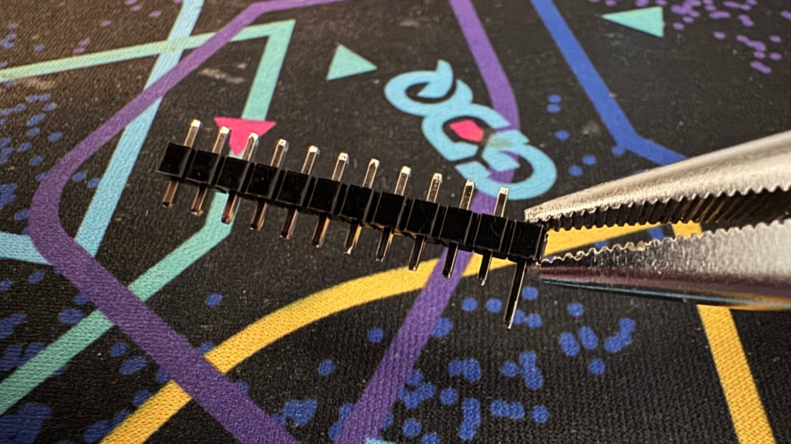
So I ended up going back to a modified machine pin header approach using the standard square pins. First I used pliers to pop off all of the pins from a set of headers.
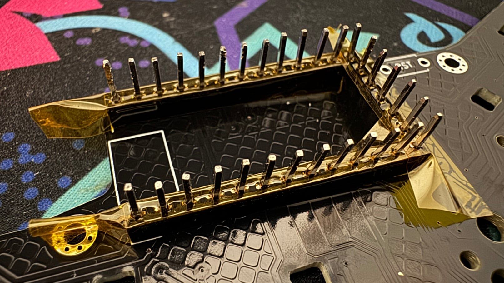
Then I laid a row of temperature-resistant Kapton tape on top of the soldered headers. It's pretty easy to poke the individual headers through the tape. You may need to rotate them a bit since they're square shaped.
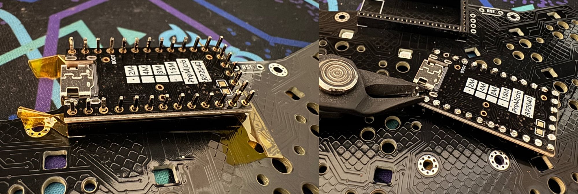
Finally you can carefully lay your RP2040 on top. (The second time I did this I realized it was easier to lay the RP2040 down first and feed the pins through it.) Now you can solder the headers into place. The Kapton tape stops you from accidentally having solder drip down and permanently fuse your microcontroller to the headers. The end result is a slightly shorter Pro Micro. You'll need to trim the excess pins off the top of the microcontroller with some angle cutters. (Scissors that cut a bit more flush than your standard pair.)
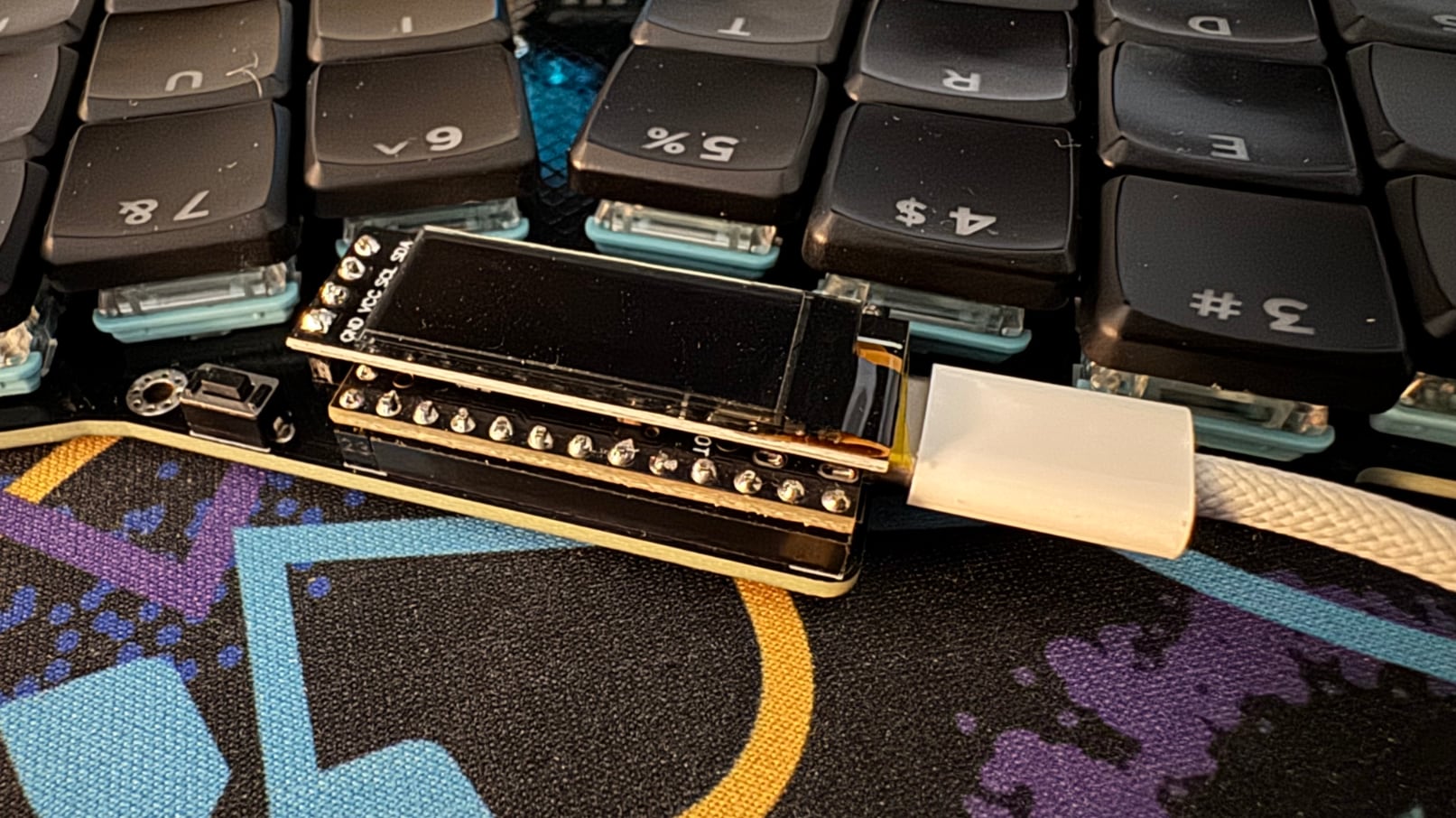
The OLED screen needs to be a bit taller than the Pro Micro, so you can use the same 3.5mm headers while keeping the plastic piece in place. You'll want to solder the OLED screen's pins in place slotted into the keyboard's actual OLED header using the Kapton trick again. It barely fits over the RP2040, and there's a chance it could be angled awkwardly in the air if you soldered it on a breadboard.
The Case

The RevXL uses a "tray" style 3D printed case with heat set inserts. It's exactly the same design featured in my Ergogen tutorial. The parametric nature of Ergogen allowed me to copy the case code over, adjust a few variables, and pop out a finished case design with very few adjustments. Score one for reusable code!
Due to how wide this particular keyboard is, the case doesn't fit on my 3D printer as a single piece. It's been split down the middle to allow it to be printed as two parts. Hence some of the interior mounting holes on the PCB. I also used the same heat set insert trick with the screws holes as discussed in the tutorial.
The Firmware

The short version of this section is that the RevXL uses the Vial fork of the QMK open source keyboard firmware project. I've previously worked primarily with the ZMK wireless keyboard firmware, but it doesn't have as robust as support as QMK for per-key RGB lighting. Vial meanwhile is an open source fork of QMK inspired by the Via project. It adds support for using a GUI on your computer to update your keyboard's keymap and settings in real time without the need to re-flash your computer.
The long version of this section is: What the heck happened to QMK?
QMK is the grandfather of modern open source keyboard firmwares. It's the longest running project with support for a dazzling amount of hardware features. While there are newer projects like ZMK targeting wireless keyboards and FAK targeting keyboards based off the CH55X chip, QMK's still the gold standard when it comes to working with wired keyboards. It's the software that companies like Keychron and Drop target when they want to try and sway mechanical keyboard folks from going the DIY route.
Working with QMK has always been a little cumbersome for reasons that are largely not their fault. The project originally targeted some of the earliest Arduino hardware. The AVR platform runs on low-level C code, and there's only so many layers of GUI niceties you can put on top of the flashing process. Once you get your head around it though, the project's not that hard to work with.
To define a matrix, you pull up the Config Options documentation, hop into config.h and set:
#define MATRIX_ROW_PINS { GP29, GP28, GP27, GP26, GP22, GP21, GP16, GP15, GP14, GP13 }
#define MATRIX_COL_PINS { GP10, GP0, GP1, GP4, GP5, GP6, GP9, GP12 }
Then you just browse over keymap.c and put the right keycodes into an array. Toss together some ASCII art of your layout in the comments and you're off to the races, right?
Well... not quite.
It's been about three years since I've used QMK. In the intervening time, the project realized that managing keyboard firmware C files written with a variety of community conventions was becoming unwieldy. They decided to move most functionality (but not all) into more structured .json files.
Well alright then. Let's pull up the info.json Reference, create an info.json file, and set out matrix definition there.
{
	[...]
    "matrix_pins": {,
        "rows": ["GP29", "GP28", "GP27", "GP26", "GP22", "GP21", "GP16", "GP15", "GP14", "GP13"],
        "cols": ["GP10", "GP0", "GP1", "GP4", "GP5", "GP6", "GP9", "GP12"]
    },
    [...]
}
Cool, everything's hunky dory now, right? Nope! QMK decided that info.json should describe common aspects of a family of keyboards. What you really need is a device specific keyboard.json file. It's a superset of info.json with a few more hardware fields.
The background and purpose of this keyboard.json file is mentioned in the 2024 May 26 Changelog, and it is referenced on the Porting Keyboards page.
That's it.

The Porting Keyboards page tells you to go to the Device Driven Configuration page for more details. This page does not mention keyboard.json once. It outlines the background of info.json and links to the info.json Reference, but it's not immediately clear what this file's relationship is to keyboard.json. I guess you're supposed to know that "There are a lot of options that can be placed in that file, too many to list here" is supposed to mean, "keyboard.json files can use info.json properties."
I know I've moved onto full on kvetching at this point. Managing open source projects the size of QMK is a difficult prospect. Writing thorough and understandable documentation is a skill unto itself. QMK's not only having to deal with keyboard designers like myself, but also beginner users who have bought a prebuilt QMK keyboard and just need assistance walking through updating their keymap. I'm fine dealing with spotty documentation if there's enough information available to get to your goals. Ergogen v4 for example still has some incomplete docs.
As it exists now however, QMK's documentation is a land mine field of outdated information. The Basic QMK Structure page is missing files. The Understanding QMK page had a guide on how to define non-standard matrix structures, something I desperately needed for my build, but it will throw depreciation errors if you actually try and implement its suggestions in your keyboard today. If you'd like to implement a rotary encoder and navigate to the Encoders page, you have made a mistake. The actual modern documentation is on the info.json Reference. Just be warned that the documentation fails to mention that the configuration won't do anything unless you add "encoder": true to the "features": section.
As a relative outsider to the QMK scene, wrapping your head around the project as it currently exists is a bit of a mess. Maybe I missed some obvious resource or example repo and this is mostly on me? I just feel like I suddenly understand why the ZMK team is working on improving their wired keyboard support. Googling for QMK answers is unfortunately also a risky proposition given the age of the project. I don't know if bumping things up to a full new "QMK 2" name would have made any of this more clear, but make sure any post you're referencing is relatively recent. Your best bet is to find a recent configuration of a keyboard with similar features to yours and copy that.
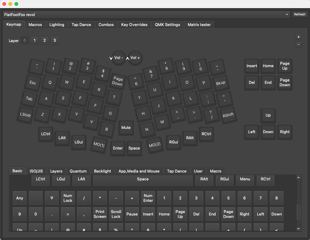
Once my QMK configuration was finally up and running, adding Vial support was nice and straightforward. Their site had step by step documentation, and they walk you through the most commonly requested features like rotary encoder and LED support. It is a bit humorous to have to build your keyboard layout out in Keyboard-Layout-Editor.com after having initially designed it in Ergogen, but the process is nice and straightforward.
Once you get Vial up and running, you can use their GUI as either an offline application or a Chrome web app to re-map your keyboard's layout on the fly. It's a nice way of letting beginners dabble with QMK, and it exposes a lot of features you might not even realize are there. If I work with QMK again, I'll definitely be taking the time to add Vial support as well.
Build of Materials
| Part | Amount | Price |
|---|---|---|
| Revxl PCB via PCBWay | 1 | $60.00 USD |
| RP2040 "Pro Micro" | 1 | $3.00 USD |
| Choc Switches | 68 | $40.00 USD |
| 1N4148 T4 Diodes | 68 | $2.00 USD |
| SK6812 MINI-E RGB LEDs | 68 | $2.00 USD |
| EC11 Rotary Encoder | 1 | $2.50 USD |
| EC11 20x15mm Knob | 1 | $3.00 USD |
| MBK Glow Keycaps | 1 | $55.00 USD |
| 6mm x 3mm x 4.3mm Pushbutton | 1 | $2.00 USD |
| Machine Pins | 39 | $6.00 USD |
| Machine Pin Headers | 39 | $4.00 USD |
| 4mm M2 Screws | 8 | $1.00 USD |
| 2mm M2 Screw Inserts | 8 | $1.50 USD |
| Bumpons | 1 Pack | $1.00 USD |
Conclusion
This was an incredibly satisfying keyboard build. Despite working with RGB LEDs and the RP2040 for the first time, I managed to design the PCB without any routing issues on my first try. (Something I've not always been lucky within the past.) I'm overall really happy how this project came together. If I had to make some adjustments for a v2 design, I would give the microcontroller a bit more space, and maybe consider adding a few more switch footprints to the arrow cluster. A few kind folks pointed out that if I fill in the 5 gaps in the current design, you would have the option of including a small numpad area in addition to an arrow cluster.
I was going to end this post with a joke about how I'd post my husband's impressions as soon as he finished learning how to type on a Choc-spaced column-staggered keyboard. He's actually taken to the RevXL like a fish to water. The cozier Choc spacing takes a bit of time to get used to, but he's already been toying with lighting patterns and updating the keymaps. Mission accomplished.